
K 2500 Suburban 4WD V8-5.7L VIN R (1999)
Control Assembly: Description and Operation
Heating and Ventilation
Heater Blower Controls Circuit Description
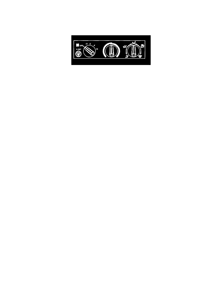
The control assembly in the instrument panel contains three rotary control knobs: the blower speed knob, the mode selection knob, and the temperature
adjustment knob. The instrument panel dimmer control controls the brightness of the dial illumination.
Temperature Rotary Knob
When the temperature rotary knob is in the full COLD or counter clockwise position, all of the air delivered by the ventilation system is unheated.
When the temperature rotary control is in the full HOT or clockwise position, all of the air passing through the heater module is heated prior to
discharge. Intermediate positions of the temperature rotary knob result in a mixture of heated and unheated air in order to provide more moderated
air temperatures.
Mode Rotary Knob
The mode rotary knob operates the defrost control cable that moves to the left end of the heater module. This cable operates a crank lever and the
shaft that controls the position of the an air valve in the heater module. The detents at 0°, 90°, and 180° indicate the VENT position, the FLOOR
position, and the DEFROST position. By placing the rotary control anywhere in between the two desired modes, the operator can blend the air
delivery.
Blower Speed Control
The blower switch provides a choice of four blower speeds and the OFF position. The blower switch receives power through the HTR-A/C FUSE
when the ignition is in the ON position. In the LO position, the circuit continues through the heater wiring harness to the two resistors in the
resistor assembly near the blower motor.
When the blower switch is in a medium-speed position, the circuit continues through the heater wiring harness to the resistor assembly, but the
circuit bypasses one of the two resistors. When the blower switch is in the HIGH position, the circuit continues through the heater wiring harness
to the resistor assembly. The circuit bypasses both resistors in order to provide full power to the blower motor.
From the resistor assembly, the circuit moves to the blower motor terminal in order to operate the blower motor. A sheet metal ground wire that
connects to a ground terminal on the cowl completes the blower motor circuit to the ground.
Modes Description
VENT MODE
When the mode rotary knob is in the VENT position, the defroster valve and the heater valve remain closed. As a result, the air coming from the
instrument panel vents should be approximately the same temperature as the outside air.
HEATER MODE
When the mode rotary knob is in the HEATER position, the defroster valve remains closed. As a result, the air from the blower fan receives heat.
This air goes to the defroster valve. The defroster valve sends most of the airflow to the heater duct, with some of the air going to the defroster
nozzle.
DEFROST MODE
When the mode rotary knob is in the DEFROST position, the defroster control cable moves the defroster valve in order to fully uncover the
opening to the defroster nozzle. This restricts the opening to the heater duct. This delivers the maximum airflow to the defroster, with only a small
amount of the airflow exiting out of the heater duct.