
K 2500 Truck 4WD V8-379 6.2L DSL VIN C FI (1989)
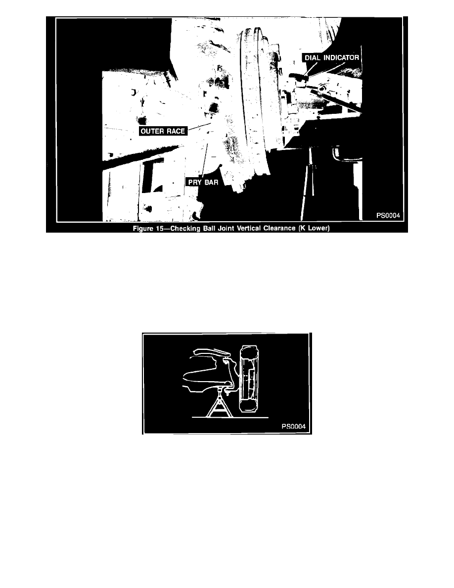
Figure 15
Check the ball joints for vertical looseness
^
With the vehicle on the jack stands, place dial indicator against the spindle to show vertical movement (figure 15).
^
Pry between the lower control arm and the outer race while reading the dial indicator. This will show vertical looseness in the ball joints (figure
15).
^
If the dial indicator reading is more than 1 mm (0.040-inch), replace the ball joint.
Figure 14 - Supporting the Lower Control Arm
NOTICE:
Do not pry between the lower arm and the drive axle seal or in such a manner that the ball joint seal is contacted. Damage to the seal will
result (4WD).
1990 C and K MODEL UPPER (Figure 14)
^
Be sure the vehicle rests on a level surface.
^
Raise and support front of vehicle with suitable safety stands. Support the lower control arm with a floor stand or jack as far outboard as
possible.
^
The vehicle must be stable and should not rock on the floor stands.
^
If the vehicle is equipped with aluminum wheels it may be necessary to first remove the wheel.