
K 2500 Truck 4WD V8-379 6.2L DSL VIN C FI (1989)
Step 3:
Remove insulation.
Step 4:
Align seal with end of cable insulation (Weather Pack(R) terminals only).
Step 5:
Position strip (and seal for Weather Pack(R)) in terminal.
Step 6:
Hand crimp core wings.
Step 7:
Hand crimp insulation wings (non-Weather Pack(R)). Hand crimp insulation wings around seal and cable (Weather Pack(R)).
Step 8:
Solder all hand crimped terminals.
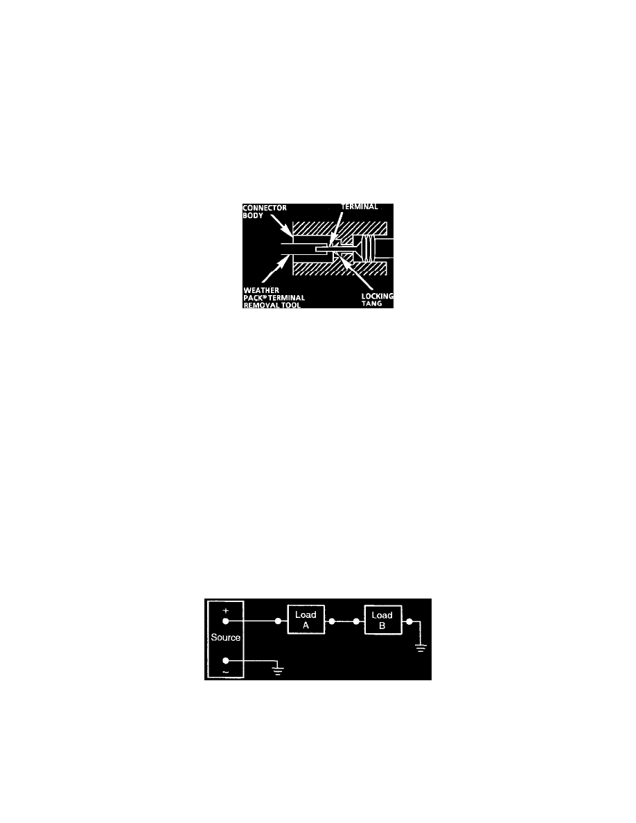
Weather Pack Connectors
Fig. 21 Typical Weather Pack Connector and Terminal
PROCEDURE
1
Separate the connector halves.
2. Open secondary lock. A secondary lock aids in terminal retention and is usually molded to the connector.
3. Grasp the lead and push the terminal to the forward most position. Hold the lead at this position.
4. Insert the Weather Pack terminal removal tool into the front (mating end) of the connector cavity until it rests on the cavity shoulder.
5. Gently pull on the lead to remove the terminal through the back of the connector.
NOTE: Never use force to remove a terminal from a connector.
6. Inspect the terminal and connector for damage. Repair as necessary.
7. Reform the lock tang and reseat terminal in connector body.
8. Close secondary locks and join connector halves.
Electricity
Electrical power flows from the power source to a load device and then back to the source of power. The electrical circuit should contain a device
to open or close the circuit, such as a switch or relay, and a protective device (in case of an overload), such as a circuit breaker or a fusible link.
Electrical circuits can be set up as series circuits, parallel circuits, or series/parallel circuits. The circuits in this vehicle are normally parallel
circuits.
Series Circuit
Series Circuit
In a series circuit, the electrical devices are connected to form one current path to and from the power source. In a series circuit the voltage is
shared equally by all the devices in the circuit.
Parallel Circuit