
K 2500 Truck 4WD V8-379 6.2L DSL VIN C FI (1989)
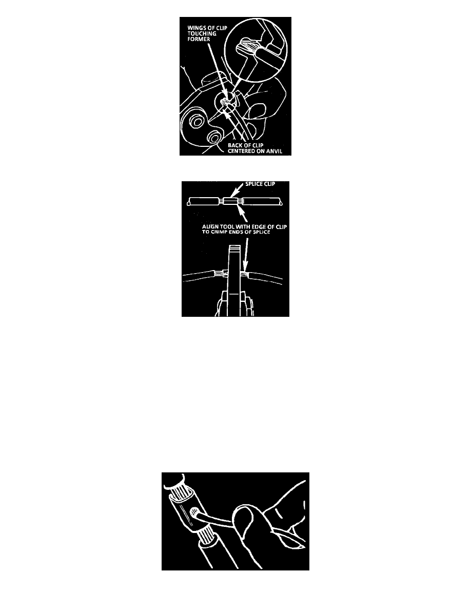
Fig. 8 Crimping the Splice Clip
Fig. 9 Completing the Crimp
Select the proper clip to secure the splice. To determine the proper clip size for the wire being spliced, follow the directions included in the J
38125-A Terminal Repair Kit. Select the correct anvil on the crimper. On most crimpers your choice is limited to either a small or large anvil.
Overlap the stripped wire ends and hold them between your thumb and forefinger as shown in Fig. 7. Then, center the splice clip under the
stripped wires and hold it in place.
^
Open the crimping tool to its full width and rest one handle on a firm flat surface.
^
Center the back of the splice clip on the proper anvil and close the crimping tool to the point where the former touches the wings of the clip.
^
Make sure that the clip and wires are still in the correct position. Then, apply steady pressure until the crimping tool closes, Fig. 8.
^
Before crimping the ends of the clip, be sure that:
^
The wires extend beyond the clip in each direction.
^
No strands of wire are cut loose, and
^
No insulation is caught under the clip. Crimp the splice again, once on each end. Do not let the crimping tool extend beyond the edge of the
clip or you may damage or nick the wires, Fig. 9.
Step 5: Solder
Apply 60/40 rosin core solder to the opening in the back of the clip, Fig. 10. Follow the manufacturer's instruction for the solder equipment you