
K 2500 Truck 4WD V8-379 6.2L DSL VIN C FI (1989)
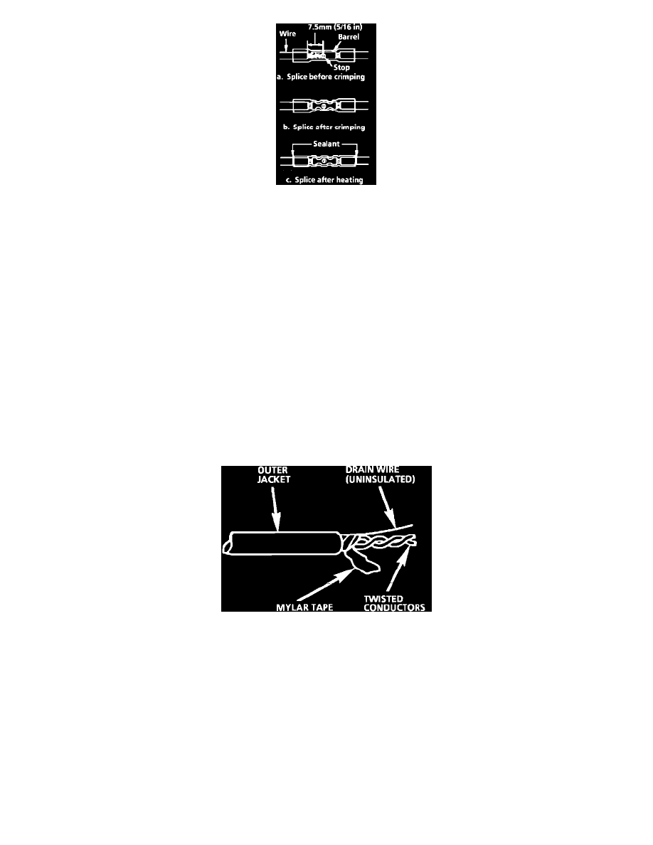
Fig. 14 Seal Splice Sequence
Step 4: Select and Position the Splice Sleeve
Select the proper splice sleeve according to wire size. The splice sleeves and tool nests are color coded. Using a crimp tool, Fig. 13, position the
splice sleeve in the proper color nest of the hand crimp tool. Place the splice sleeve in the nest so that the crimp falls midway between the end of
the barrel and the stop.
The sleeve has a stop in the middle of the barrel to prevent the wire from going further, Fig. 14. Close the hand crimper handles slightly to hold the
splice sleeve firmly in the proper nest.
Step 5: Insert Wires into Splice Sleeve and Crimp
Insert the wire into the splice sleeve until it hits the barrel stop and close the handles of the crimper tightly until the crimper handles open when
released. The crimper handles will not open until the proper amount of pressure is applied to the splice sleeve. Repeat steps 4 and 5 for opposite
end of the splice.
Step 6: Shrink the Insulation around the Splice
Using the Ultratorch J 38125-5 (follow instructions that accompany Ultratorch), apply heat where the barrel is crimped. Gradually move the heat
barrel to the open end of the tubing, shrinking the tubing completely as the heat is moved along the insulation. A small amount of sealant will come
out of the end of the tubing when sufficient shrinking is achieved, Fig. 14.
Splicing Twisted/Shielded Cable
Fig. 15 Twisted/Shielded Cable
Twisted/shielded cable is sometimes used to protect wiring from electrical noise (stray signals). For example, two-conductor cable of this construction is
used between the ECM and the distributor. See Fig. 15 for a breakdown of twisted/shielded cable construction.
Step 1: Remove Outer Jacket
Remove the outer jacket and discard it. Be careful to avoid cutting into the drain wire or the mylar tape.
Step 2: Unwrap the Tape
Unwrap the aluminum/mylar tape, but do not remove it. The tape will be used to rewrap the twisted conductors after the splices have been
made.
Step 3: Prepare the Splice