
K 2500 Truck 4WD V8-393 6.5L DSL (1994)
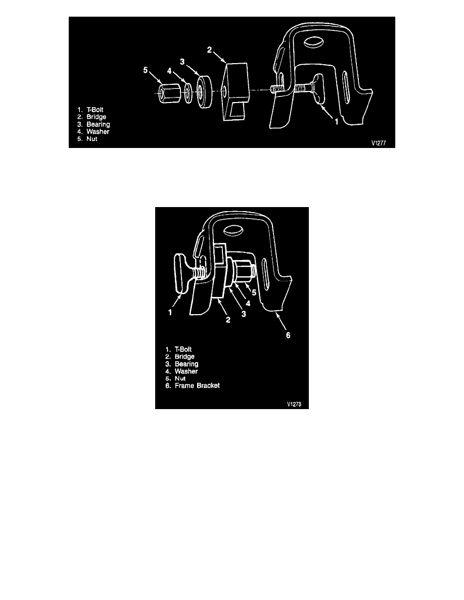
Knockout Tool Components
5. Frame bracket knockout using tool J 38794.
^
Do not distort the frame bracket when removing the knockout.
^
Apply extreme pressure lubricant to the threads of the T-bolt and insert the bolt through the knockout hole in the bracket support.
Knockout Too Intalled Inside Bracket
^
Install bridge onto the T-bolt. The forward bracket requires the bridge to be installed between the legs of the bracket due to access problems.
^
Assemble the bridge, bearing (chamfered side out), washer, and nut in order.
^
The T-bolt head and bridge must line up horizontally with the knockout; the bridge should span the knockout without interfering with the
knockout procedure.
^
Tighten the T-bolt head against the knockout by turning the nut at the opposite end using a socket and torque wrench.
^
An open end or adjustable wrench may be needed to prevent the T-bolt from losing horizontal alignment with the knockout.
NOTICE: Do not subject the tool to more than 100 N.m (75 lbs. ft.) torque. Exceeding the recommended torque may damage the tool and/or the
bracket.
^
If the torque limit on the T-bolt is met and the knockout does not break free, use a die grinder of appropriate size. Using the stamped outline as
a guide, remove the knockout. (Remove the wax coating in the knockout area to make the perforation lines more visible).
^
If the outline is not visible, use the T-bolt head installed horizontally, as a template, and scribe the frame bracket.
^
Repeat the procedure on the other upper control arm frame bracket.
Install or Connect