
K 2500 Truck 4WD V8-454 7.4L VIN J SFI (1997)
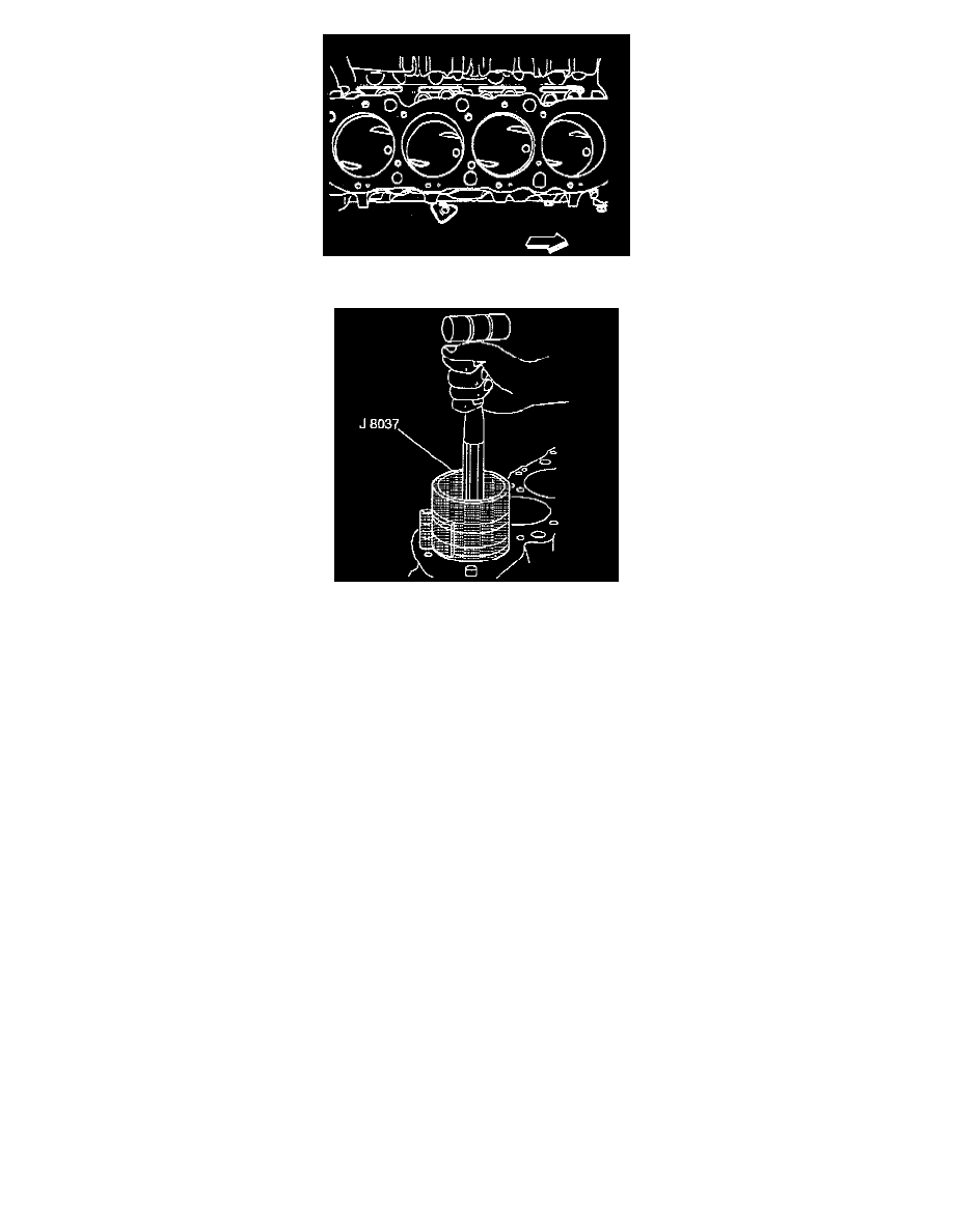
8. Ensure that the dimple faces the front of the block.
NOTE: Each connecting rod and bearing cap should be marked for proper location and orientation. Cylinder 1, 3, and 7 are the right bank and 2,
4, 6, and 8 are the left bank (when viewed from the front of the engine). The numbers on the connecting rod and bearing cap must be on the same
side when installed in the cylinder bore. If a connecting rod is ever transposed from one block or cylinder to another, new connecting rod bearings
should be fitted and the connecting rod should be numbered to correspond with the new cylinder number.
9. Install the piston and the connecting rod to the proper bore.
10. Use a hammer handle to lightly tap the piston down into the cylinder bore.
11. While tapping the piston into the bore, guide the connecting rod into position on the crankpin, using the connecting rod guide tool.
The connecting rod bearings are of the precision insert type and do not use shims for adjustment. If the clearances are excessive, the new upper
and the lower bearings will be required. The service bearings are available in the standard size and an undersize.
^
0.001 inch
^
0.002 inch
^
0.010 inch
^
0.020 inch
The selective fitting of the connecting rod bearings are necessary in production in order to obtain close tolerances. For this reason, you may
use one-half of a standard connecting rod bearing with one-half of a undersize connecting rod bearing.
4. Remove the connecting rod and the piston out of the top of the engine block using the connecting rod guide tool.
5. Remove the remaining piston and the connecting rod assemblies.