
K 2500 Truck 4WD V8-454 7.4L VIN J SFI (1997)
Electrical Group
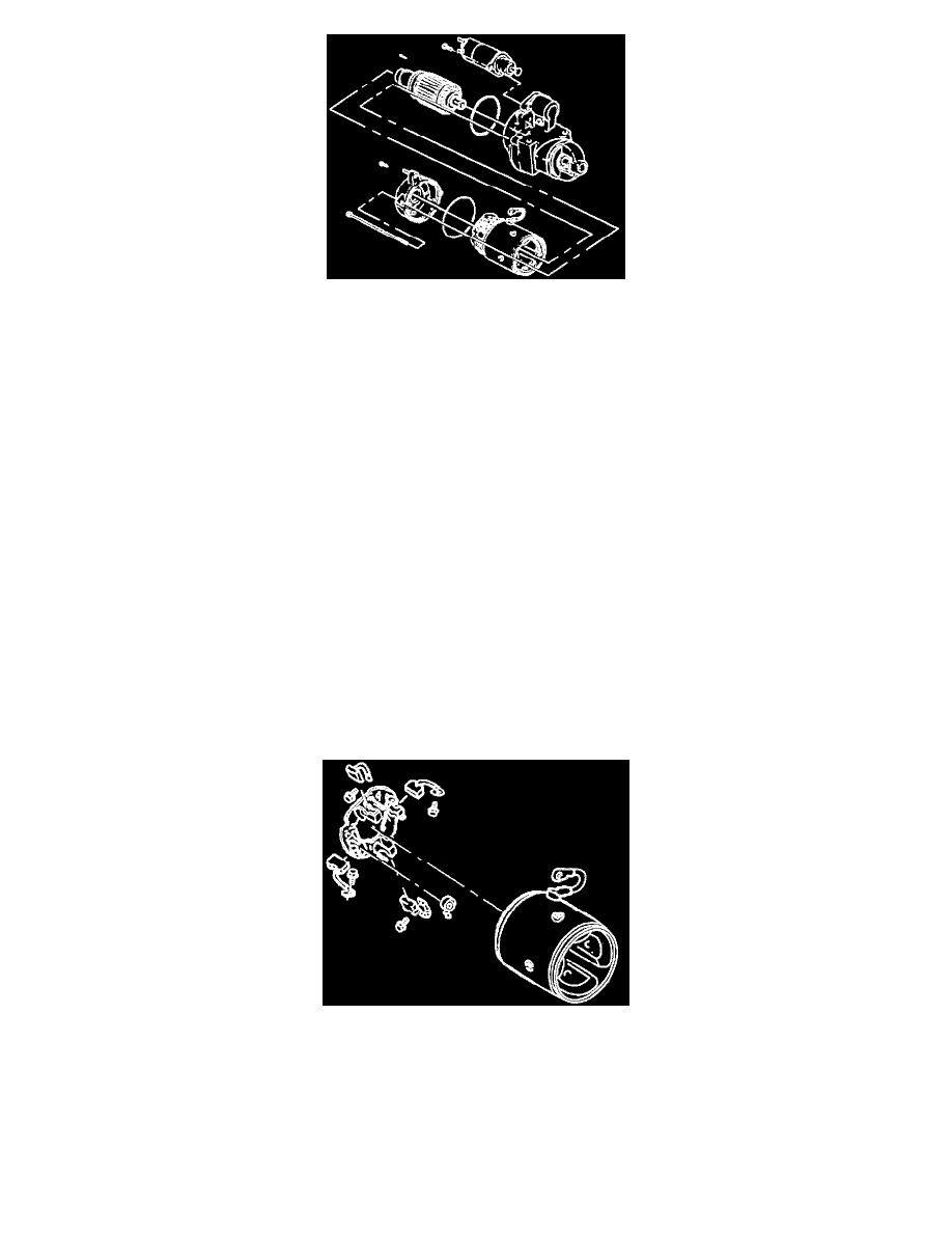
DISASSEMBLE
-
Scribe marks completely down one side of the starter motor to ensure proper alignment of all components during assembly. Use a colored pencil
or marker that will show on all parts.
1. Motor lead on the frame assembly from the solenoid assembly.
-
Remove the nut from the motor terminal, slip off the motor lead, and reinstall the nut.
2. Two through-bolts.
3. Two brush plate screws.
4. Commutator end frame and O-ring seal.
IMPORTANT
-
In the following Step, take care not to lose the small dowel pin installed between the frame assembly and the gear reduction and drive group.
The dowel pin is needed for assembly and must be saved. if it is lost, it must be replaced with a 2 mm x 10 mm (0.079 in x 0.394 in) long pin
obtained or manufactured locally.
5. Frame, field, and brush holder group, dowel pin, and O-ring seal.
-
The armature assembly may come off with the frame, field, and brush holder group or may be retained by the gear reduction and drive group.
6. Armature assembly with bearings.
-
Do not remove the bearings from the armature assembly unless replacement is required, refer to "Cleaning, Inspection, and Repair". See:
Cleaning, Inspection, and Repair
7. Solenoid screws.
8. Solenoid assembly.
-
Pivot the inside end of the solenoid assembly out of engagement shift lever drive group to withdraw it.
Frame, Field, and Brush Holder Group
Frame, Field And Brush Holder Group
DISASSEMBLE
1. Insulated brush screws.
-
Move the brush holder assembly with brushes slightly away from the frame and field assembly to reach across with a screwdriver and remove
the screws.
2. Frame and field assembly.
3. Grounded brush screws.
4. Brushes if they need replacement.