
K 2500 Truck 4WD V8-6.5L DSL Turbo VIN S (1998)
Rocker Arm Assembly: Service and Repair
REMOVAL PROCEDURE
IMPORTANT: Rotate the engine until the mark on the crankshaft balancer is at the 2 o'clock position.
Rotate the crankshaft counter clock wise 88 mm (3 1/2 inch), aligning the crankshaft balancer mark with the first lower water pump bolt, about 12:30.
This will position the engine so that no valves are close to the piston crown.
1. Disconnect the battery negative cables from the batteries.
2. Remove the upper intake manifold from the lower intake manifold.
3. Remove the lower intake manifold from the cylinder heads.
4. Remove the valve rocker arm cover from the cylinder head.
NOTICE: All valve train components must be reassembled in the exact order and position from which they were removed.
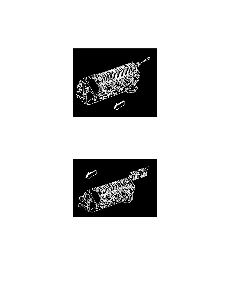
5. Remove the valve rocker arm shaft bolts from the cylinder head.
6. Remove the valve rocker arm shaft with the valve rocker arm.
IMPORTANT: The push rods must be installed in the original direction as disassembly. This is because the push rods have different degrees of
hardness at each end. A paint stripe identifies the upper end of the push rod. If the paint stripe is not visible, mark the push rod on the upper end as
the push rods are removed.