
K 2500 Truck 4WD V8-6.5L DSL Turbo VIN S (1998)
1. Install the insulator, the spacer, and the retainer on the support crossmember.
2. Install the support crossmember assembly on the frame, rearward of the mounting holes
3. Install the torsion bars.
3.1. Make sure the bars are installed on the proper sides.
3.2. Slide the support crossmember forward until the torsion bars are supported.
4. Install the adjustment arms on the torsion bars.
5. Install the bolts and the nuts into the torsion bar support crossmember.
Tighten
5.1. Tighten the center nut to 24 Nm (18 ft. lbs.).
5.2. Tighten the edge nuts to 62 Nm (46 ft. lbs.).
NOTICE: Always use the correct fastener in the proper location. When you replace a fastener, use ONLY the exact part number for that
application. The manufacturer will call out those fasteners that require a replacement after removal. The manufacturer will also call out the
fasteners that require thread lockers or thread sealant. UNLESS OTHERWISE SPECIFIED, do not use supplemental coatings (paints, greases, or
other corrosion inhibitors) on threaded fasteners or fastener joint interfaces. Generally, such coatings adversely affect the fastener torque and joint
clamping force, and may damage the fastener. When you install fasteners, use the correct tightening sequence and specifications. Following these
instructions can help you avoid damage to parts and systems.
6. Install the adjustment retainer plate and the bolt on both torsion bars.
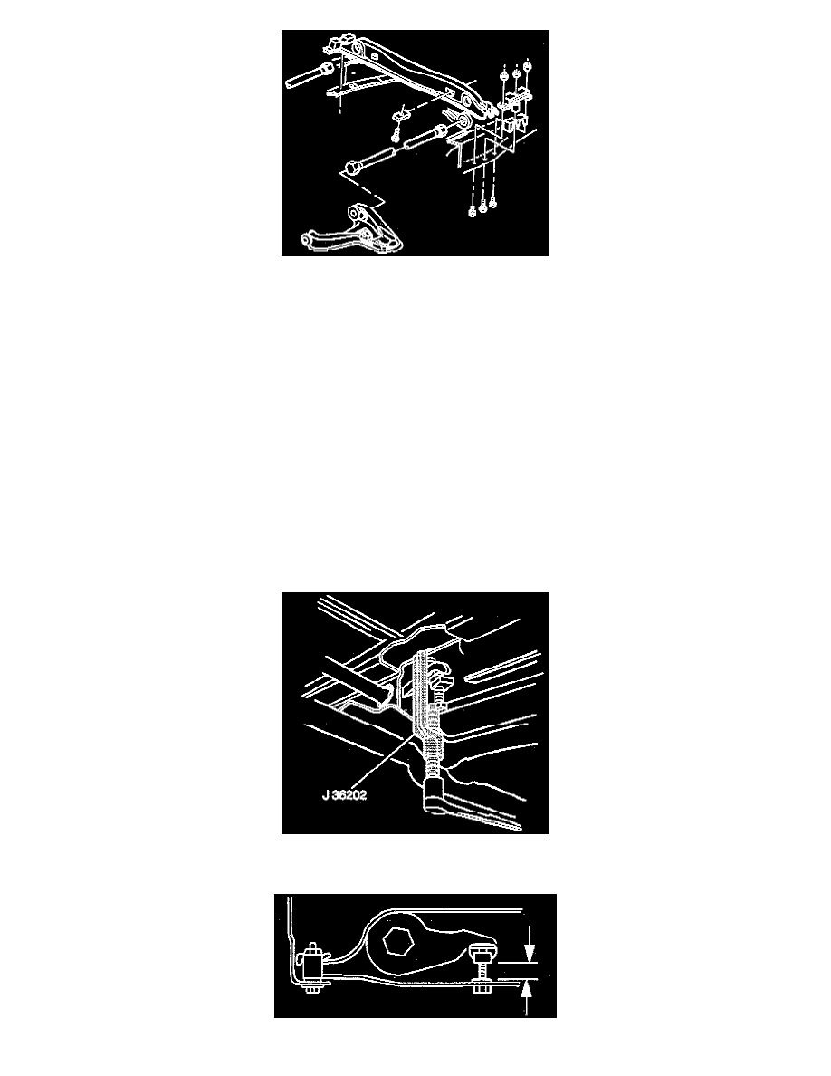
7. Using the J 36202, increase the tension on the torsion bar.
8. Install the retaining plate and the adjustment bolt.