
K 2500 Yukon 4WD V8-6.0L VIN U (2000)
Hydraulic Control Assembly - Antilock Brakes: Service and Repair
Brake Pressure Modulator Valve Replacement
Removal Procedure
Caution: Unless directed otherwise, the ignition and start switch must be in the OFF or LOCK position, and all electrical loads must be OFF before
servicing any electrical component. Disconnect the negative battery cable to prevent an electrical spark should a tool or equipment come in contact
with an exposed electrical terminal. Failure to follow these precautions may result in personal injury and/or damage to the vehicle or its components.
For Vehicles equipped with OnStar® (UE1) with Back Up Battery:
The Back Up Battery is a redundant power supply to allow limited OnStar® functionality in the event of a main vehicle battery power disruption
to the VCIM (OnStar®module). Do not disconnect the main vehicle battery or remove the OnStar® fuse with the ignition key in any position other
than OFF. Retained accessory power (RAP) should be allowed to time out or be disabled (simply opening the driver door should disable RAP)
before disconnecting power. Disconnecting power to the OnStar® module in any way while the ignition is On or with RAP activated may cause
activation of the OnStar® Back-Up Battery (BUB) system and will discharge and permanently damage the back-up battery. Once the Back-Up
Battery is activated it will stay on until it has completely discharged. The BUB is not rechargeable and once activated the BUB must be replaced.
1. Remove the negative battery cable.
Important: The area around the electric hydraulic control unit (EHCU) MUST be free from loose dirt to prevent contamination of disassembled ABS
components.
2. Thoroughly wash all contaminants from around the EHCU.
3. Disconnect the three electrical harness connectors from the electronic brake control module (EBCM).
Important: Make sure that brake lines are tagged and kept in order for proper reassembly.
4. Disconnect the 5 brake lines from the brake pressure modulator valve (BPMV). When looking at the brake pipe port face of the BPMV, the ports
are assigned as follows:
-
Upper Left--Left Front Output.
-
Upper Middle--Right Front Output.
-
Upper Right--Rear Output.
-
Lower Left--Master Cylinder Secondary/Front Input.
-
Lower Right--Master Cylinder Primary/Front Input.
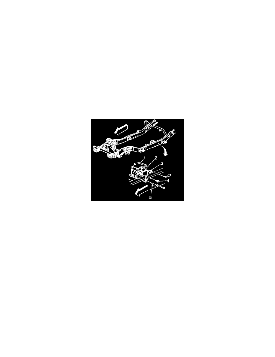
5. Remove the 3 bolts (4) securing the EHCU mounting bracket (3) to the frame rail (5).
6. Remove the EHCU (1) from the vehicle.