
K 2500 Yukon 4WD V8-6.0L VIN U (2000)
Fusible Link
Fusible link is wire designed to melt and break continuity when excessive current is applied. It is often located between or near the battery and starter or
electrical center. Use a continuity tester or a J 39200 DMM at each end of the wire containing the fusible link in order to determine if it is broken. If
broken, it must be replaced with fusible link of the same gage size.
Repairing a Fusible Link
IMPORTANT: Fusible links cut longer than 225 mm (approx. 9 inches) will not provide sufficient overload protection.
Refer to Splicing Copper Wire Using Splice Clips.
Repairing Damaged Wire Insulation
If the conductive portion of the wire is not damaged, locate the problem and apply tape around the wire. If the damage is more extensive, replace the
faulty segment of the wire. Refer to Splicing Copper Wire Using Splice Clips and follow the instruction to repair the wire.
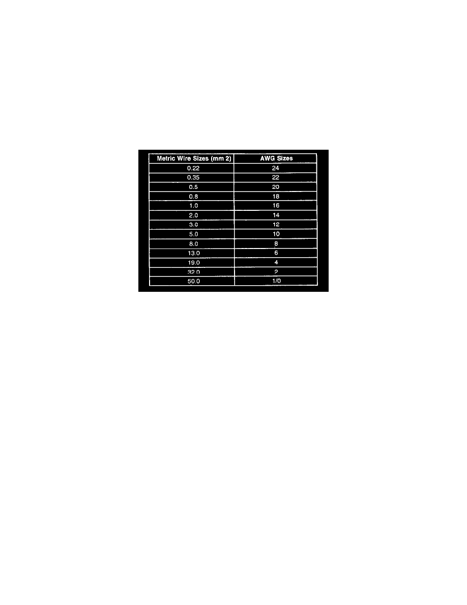
Wire Size Conversion
Wire Size Conversion
Connector Position Assurance (CPA)
The connector position assurance (CPA) is a small plastic insert that fits through the locking tabs of all the SIR/SRS system electrical connectors. The
CPA ensures that the connector halves cannot vibrate apart. You must have the CPA in place in order to ensure good contact between the SIR/SRS
mating terminals.
Inducing Intermittent Fault Conditions
In order to duplicate the customer's concern, it may be necessary to manipulate the wiring harness if the malfunction appears to be vibration related.
Manipulation of a circuit can consist of a wide variety of actions, including:
-
Wiggling the harness
-
Disconnecting a connector and reconnecting
-
Stressing the mechanical connection of a connector
-
Pulling on the harness or wire in order to identify a separation/break inside the insulation
-
Relocating a harness or wires
All these actions should be performed with some goal in mind. For instance, with a scan tool connected, wiggling the wires may uncover a faulty input to
the control module. The snapshot option would be appropriate here. Refer to Scan Tool Snapshot Procedure. You may need to load the vehicle in order
to duplicate the concern. This may require the use of weights, floorjacks, jackstands, frame machines, etc. In these cases you are attempting to duplicate
the concern by manipulating the suspension or frame. This method is useful in finding harnesses that are too short and their connectors pull apart enough
to cause a poor connection. A DMM set to Peak Min/Max mode and connected to the suspect circuit while testing can yield desirable results. Refer to
Testing for Electrical Intermittents.
Certainly, using the senses of sight, smell, and hearing while manipulating the circuit can provide good results as well.
There may be instances where circuit manipulation alone won't meet the required criteria for the fault condition to appear. In such cases it may be
necessary to expose the suspect circuit to other conditions while manipulating the harness. Such conditions would include high moisture conditions,
along with exceptionally high or low temperatures. The following discusses how to expose the circuit to these kinds of conditions.
Salt Water Spray