
K 2500 Yukon 4WD V8-6.0L VIN U (2000)
-
Tighten the nuts to 190 Nm (140 ft. lbs.).
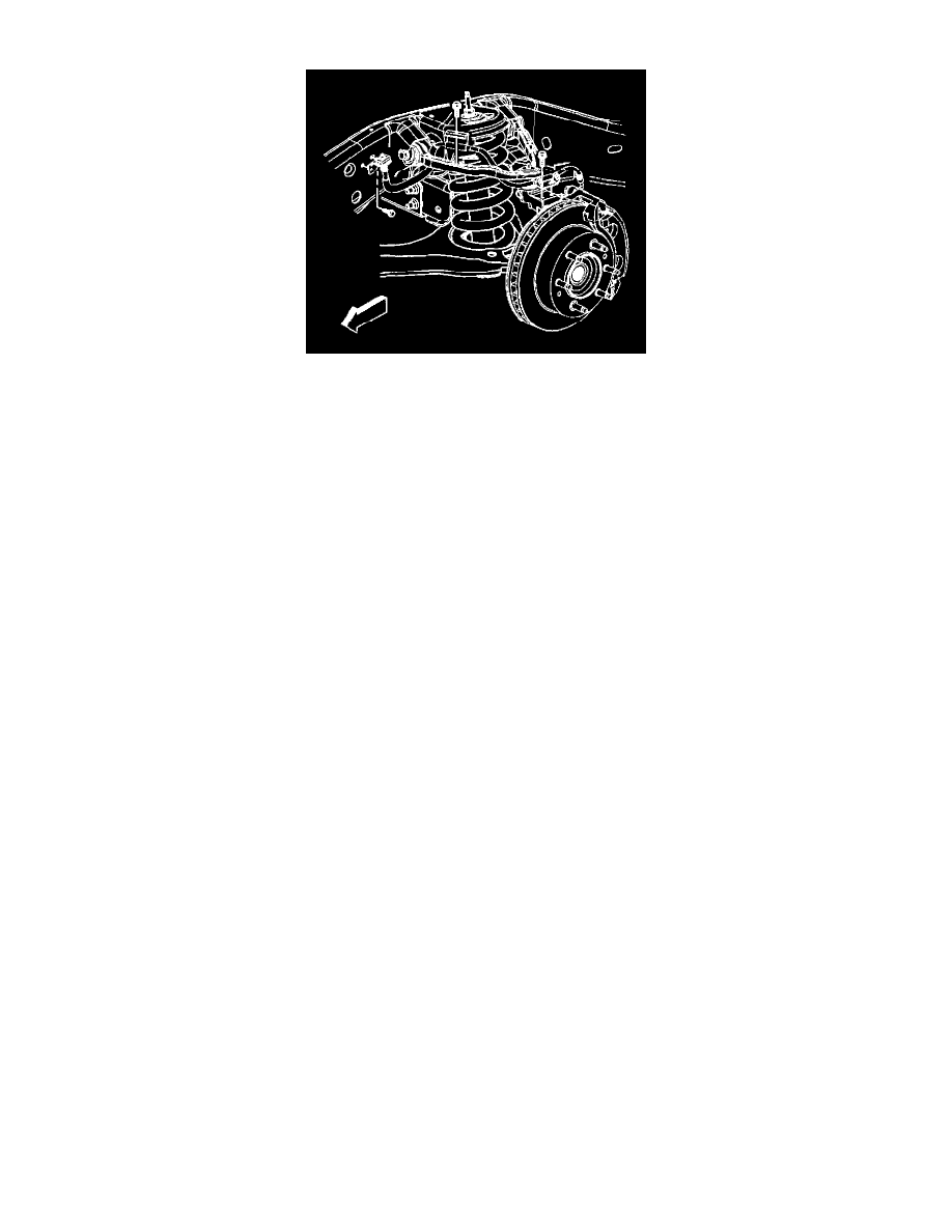
6. Connect the upper control arm to the steering knuckle.
7. Install the halfshaft. Refer to Wheel Drive Shaft Replacement in Wheel Drive Shafts.
8. Install the new nut to the upper ball joint stud.
-
Tighten the nut to 50 Nm (37 ft. lbs.).
9. Install the retaining bolts for the brake hose and wheel speed sensor brackets.
-
Tighten the bolts to 9 Nm (80 inch lbs.).
10. Connect the RTD link rod to the sensor (if equipped). Refer to Front Position Sensor Link Assembly Replacement - Electronic Suspension.
11. Install the tire and wheel assembly. Refer to Tire and Wheel Removal and Installation in Wheels, Tires and Alignment.
12. Remove the safety stands.
13. Lower the vehicle.
14. Verify the wheel alignment. Refer to Wheel Alignment Specifications (RWD Pick-up) or Wheel Alignment Specifications t4WD Pick-up) or
Wheel Alignment Specifications (RWD Utilities) or Wheel Alignment Specifications (4WD Utilities).