
K 3500 Truck 4WD V8-393 6.5L DSL Turbo (1993)
Throttle Position Sensor: Adjustments
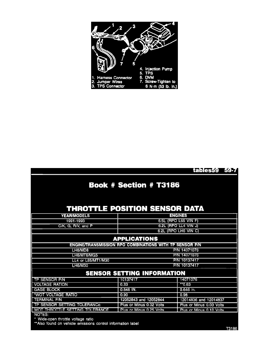
Connecting Digital Multimeter
NOTE: This procedure is updated by TSB# 932486C, dated JUNE 1993.
1. Remove air cleaner assembly and related hoses.
2. Disconnect the TP sensor connector and insert jumper wires between TP sensor and harness.
-
Jumpers can be made using terminals P/N 12052843 and 12052844. Three jumper wires or their equivalent will be necessary.
3. Turn key to "ON", engine not running.
4. Using a digital multimeter J 39200 or equivalent:
^
Measure the voltage from the TP sensor connector terminals "A" to "C". This is the voltage reference.
^
Multiply the voltage ratio number X voltage reference number from step #4. The resulting product is the desired TP sensor voltage setting.
Example: 0.33 (voltage ratio x 4.97 (voltage reference) = 1.64 (desired voltage setting)
NOTE: Refer to the "Throttle Position Sensor Data" chart for calculating the correct TP sensor voltage setting for all adjustments.