
K 3500 Truck 4WD V8-393 6.5L DSL Turbo (1993)
Installing Gage Block
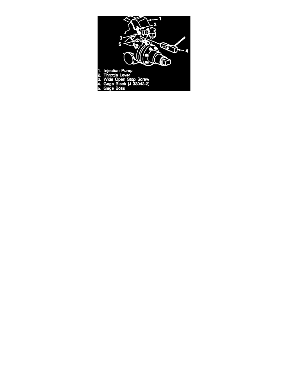
5. Insert the 0.646 side of the TP sensor/VRV gage block, (P/N J 33043-2), between the gage boss on the injector pump and the wide open stop
screw on the throttle lever.
6. Rotate the throttle lever toward the wide open throttle (WOT) position so that the gage block is held firmly in place.
7. Measure the voltage between terminals "B" and "C". This is the TP sensor voltage. It must be within the specified tolerance of the desired TP
sensor voltage setting. Refer to the "Throttle Position Sensor Data" chart.
Example:
^
The actual TP sensor voltage for TP sensor (GM P/N 10137417) should be between 1.62 volts and 1.66 volts.
^
For engines equipped with (GM P/N 14071076) TP sensor voltage is between 3.10 and 3.16 volts.
8. If the TP sensor voltage is within tolerance, then proceed to step #11.
9. To adjust the TP sensor:
^
Loosen the two attaching screws
^
Rotate the TP sensor to the full left position (counter-clockwise position - facing sensor).
^
Rotate the sensor back to the right (clockwise) until the desired TP sensor voltage setting (from step #4) is obtained.
NOTE: To obtain the correct position, the sensor must be rotated to the right from its full left position.
10. When the correct voltage is obtained, hold TP sensor in this position and tighten the TP sensor attaching screws.
Torque Value:
6 Nm (53 in lb)
11. Release throttle lever and allow it to return to the idle position. Open the throttle lever back against the gage block and recheck the TP sensor.
It must be within the specified tolerance of the required TP sensor voltage. Return to step 9 if adjustment necessary.
12. Once the TP sensor has been set, the WOT setting must be checked.
^
Multiply the WOT voltage ratio X voltage reference (from step 4) = required WOT voltage.
Example: 0.90 (WOT ratio) x 4.97 volts (voltage reference) = 4.47 volts (TP sensor voltage). Refer to the "Throttle Position Sensor Data"
chart for correct TP sensor part number.
13. To measure the actual WOT voltage:
^
Remove the 0.646 gage block.
^
Move and hold throttle to WOT.
^
Check voltage. It must be within the WOT voltage setting tolerance for the TP sensor specified.
Example:
^
For engines equipped with TP sensor (GM P/N 10137417) acceptable WOT voltage is between 4.22 to 4.72 volts.
^
For engines equipped with TP sensor (GM P/N 14071076) acceptable WOT voltage is between 4.77 to 4.97 volts.
14. If adjustment is not possible, or if TP sensor voltage at WOT position is not within the acceptable range, replace the TP sensor and repeat the
adjustment procedure again.
15. Turn engine control switch (key) to "OFF".
16. Remove jumper wires and reconnect TP sensor to the vehicle wiring harness.
17. Reinstall air cleaner assembly and related hoses.