
K 3500 Truck 4WD V8-393 6.5L DSL Turbo (1993)
VSS Circuit
CIRCUIT DESCRIPTION
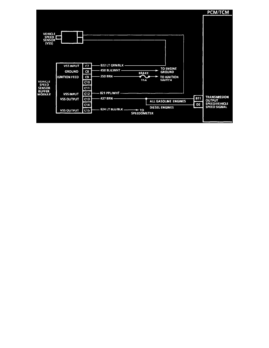
The Vehicle Speed Sensor (VSS) circuit consists of a magnetic induction type sensor, vehicle speed sensor buffer module, and wiring. Gear teeth
pressed on the outside diameter of the output carrier assembly induce an alternating current in the sensor. This current is transmitted to the buffer
module where it is passed on to the PCM/TCM. The buffer module compensates for various axle ratios and converts the signal to a square wave
for use by the speedometer, cruise control and antilock brake system.
TEST DESCRIPTION
Number(s) below refer to circled number(s) on the diagnostic chart.
1. This test checks the vehicle speed sensor signal to the PCM/TCM.
2. This test checks the vehicle speed sensor signal to the buffer module.
3. This test checks the vehicle speed sensor signal.
DIAGNOSTIC AIDS
-
Check all connections at the transmission pass-thru connector.
-
If the input sensor is not functioning at start up, it will cause the output sensor to display zero.
-
While DTC 24 is set the scan tool will display an RPM derived from input speed.