
K 3500 Truck 4WD V8-454 7.4L VIN J SFI (1996)
Fuel Injector: Description and Operation
Diagram
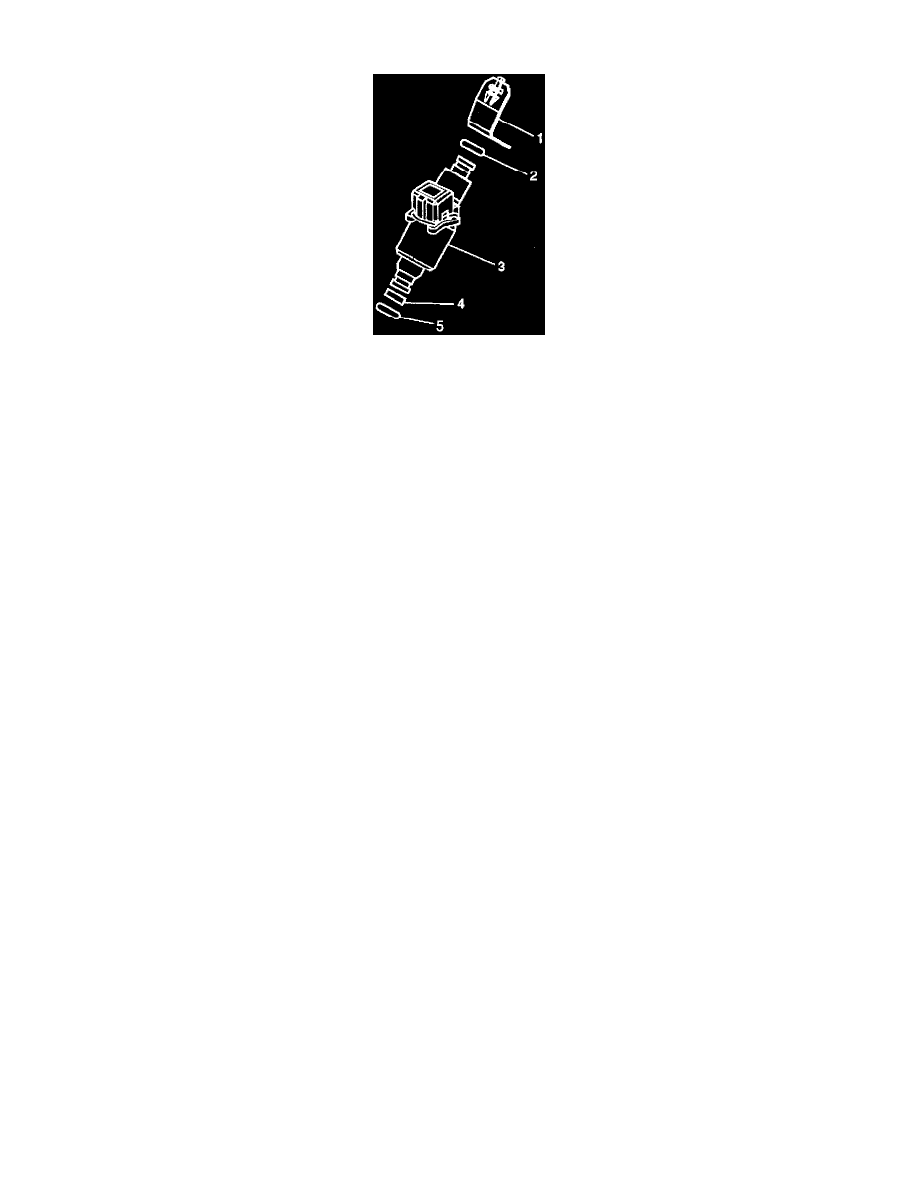
Fuel Injector Assembly
NOTE: This composite fuel rail design utilizes a unique injector clip design. This clip design does not permit the rail and injector assembly to be
pressurized with fuel pump pressure when the rail assembly is not secured in the engine manifold. Pressurizing the rail assembly without the injector
secured in the engine manifold may cause high pressure fuel to bypass the upper injector O-ring seal resulting in a fuel leak.
NOTE: Do Not apply fuel pressure to the fuel rail assembly unless the fuel rail assembly is properly secured in the engine manifold.
Operation
The fuel injector assembly is a solenoid-operated device, controlled by the VCM, that meters pressurized fuel to a single engine cylinder. The VCM
energizes the injector solenoid, which opens a ball valve, allowing fuel to flow past the ball valve and through a recessed flow director plate. The
director plate has machined holes that control the fuel flow, generating a conical spray pattern of finely atomized fuel at the injector tip. Fuel is directed
at the intake valve, causing it to become further atomized and vaporized before entering the combustion chamber.
An injector that is stuck partly open would cause loss of pressure after engine shut down, so long cranking times would be noticed on some engines.
Dieseling could also occur because some fuel could be delivered to the engine after the ignition is turned OFF.
Legend
(1) SFI Fuel Injector Retainer Clip.
(2) SFI Fuel Injector Upper O-ring.
(3) SFI Fuel Injector Assembly.
(4) Back-up O-ring.
(5) SFI Fuel Injector Lower O-ring.