
K 3500 Truck 4WD V8-5.7L VIN R (1998)
Removing Knock Sensor Module From PCM
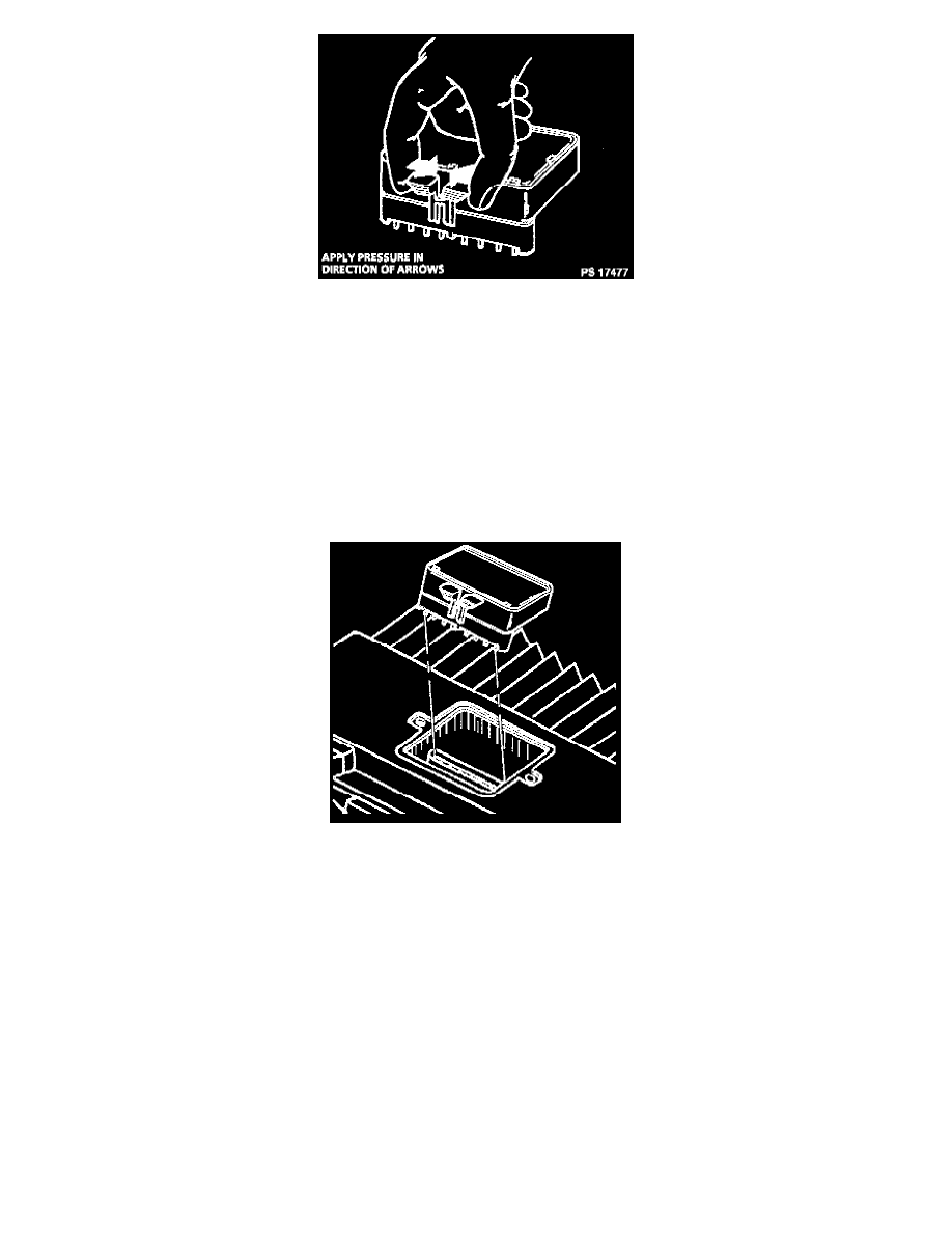
6. Remove the PROM/Electronic Spark Control Module by gently squeezing the PROM locks together.
INSTALLATION PROCEDURE
IMPORTANT:
-
Press only on the ends of the PROM/Electronic Spark Control Module. Gently press on the PROM until it is firmly seated in the socket. Listen for
the click.
-
In order to prevent possible electrostatic discharge (ESD) damage to the VCM, do not touch the connector pins or soldered components on the
circuit board.
1. Align the notches of the PROM/Electronic Spark Control Module with the notches in the PROM socket.
2. Install the PROM in the PROM socket.
3. Install the access cover on the VCM.
4. Install the VCM in the engine compartment.
5. Install the retaining spring over the edge of the VCM.
6. Install the connectors to the VCM.
7. The MIL, antilock and brake lamps will continue to be enabled until the VCM is programmed. Once the programming is complete, the lamps will
turn off and normal operation will occur.
8. Connect the negative battery cable.
9. Proceed to the VCM programming.
VCM PROGRAMMING
1. Take the following steps in order to set-up for the VCM (EEPROM) Programming.
^
The battery is fully charged.
^
The ignition is ON.
^
The Data Link Connector (DLC) is secure.
2. Refer to up-to-date Techline terminal and equipment user's instructions in order to program the VCM.
3. If the VCM fails to program, do the following functions:
^
Check all the VCM connections.
^
Check the Techline terminal and equipment for the latest software version.
^
Try again-to program the VCM. If it fails again, replace the VCM.