
K 3500 Truck 4WD V8-6.5L DSL Turbo VIN S (1999)
Control Arm: Service and Repair
Front Lower
REMOVAL PROCEDURE
-
Tools Required
-
J 24319-B Steering Linkage Puller
-
J 36202 Torsion Bar Loading/Unloading Tool
-
J 36607 Ball Joint Separator
-
J 36618 Lower Control Arm Bushing Service Set (Series 30)
-
J 9519-23 Ball Joint C-Clamp
1. Raise the vehicle. Support the vehicle with suitable safety stands.
2. Remove the tire and wheel assembly.
3. Unload the torsion bar using the J 36202.
3.1. Mark the adjuster bolt for installation.
3.2. Slide the bar forward in order to remove the adjuster arm.
3.3. Remove the adjuster arm.
-
Refer to Torsion Bar and Support Assembly Replacement.
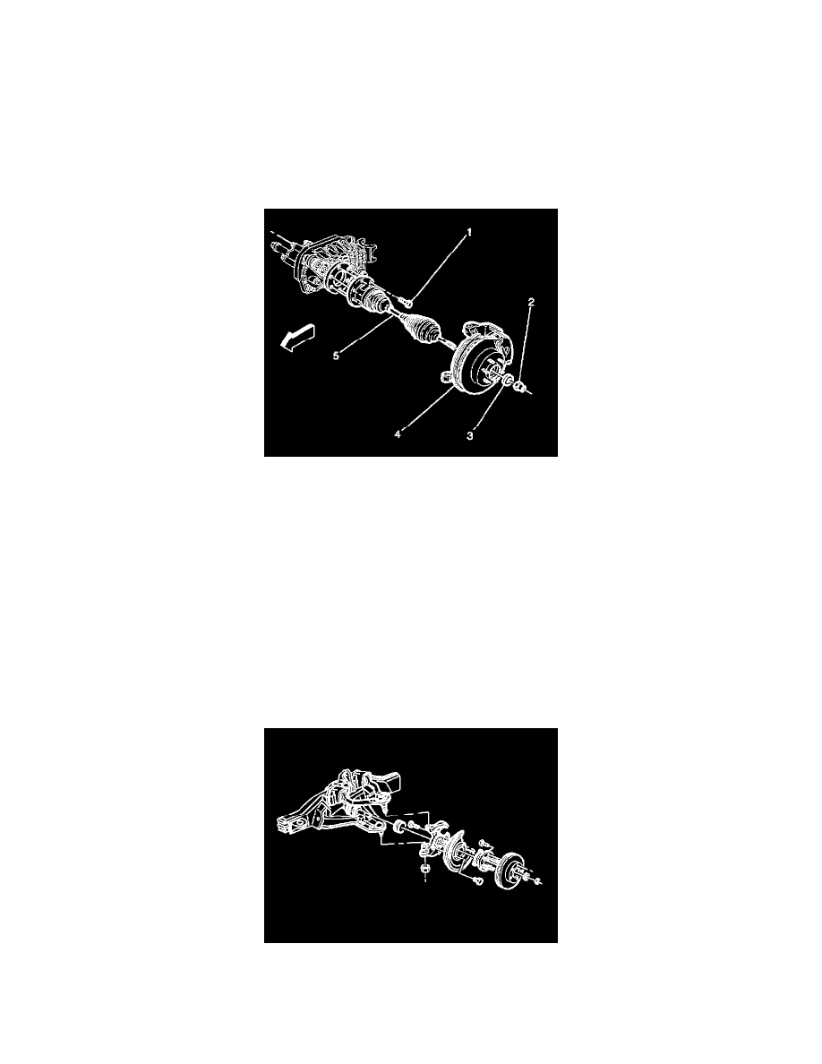
4. Remove the outer axle shaft nut (2) and the washer (3) from the hub assembly (4).
5. Remove the brake caliper.
6. Remove the brake rotor.
7. Remove the lower shock absorber bolt from the control arm. Compress the shock.
8. Using the J 24319-B, disconnect the inner tie rod end from the relay rod.
9. Support the lower control arm with a jack.
10. Remove the stabilizer link from the control arm.
11. Remove the halfshaft assembly (5).
12. Remove the cotter pin and the nut from the upper ball joint.
13. Using the J 36607, disconnect the upper ball joint from the knuckle.