
K 3500 Truck 4WD V8-6.5L DSL Turbo VIN S (1999)
1. Using the J 36618 and the J 9519-23, install the front bushing.
-
This applies to the K3 vehicle only.
-
After installing the bushing, crimp the bushing in place.
2. Using the J 36618 and the J 9519-23, install the rear bushing.
3. Install the lower control arm and the knuckle assembly to the crossmember and the frame bracket. Install the front leg of the lower control arm into
the crossmember before installing the rear leg into the frame bracket.
4. Install the bolts in the direction shown.
-
Tighten the front nut prior to tightening the rear nut.
5. Install the new nuts.
-
Tighten the nuts to 165 Nm (121 ft. lbs.).
Notice: Refer to Fastener Notice in Service Precautions.
Important: Tighten the nuts with the control arm at the proper Z height. Refer to Trim Height Inspection Procedure under Alignment.
6. Prelube the steering knuckle seal.
7. Start the drive axle through the hub.
8. Connect the ball joint to the knuckle.
9. Install the ball joint nut.
-
Tighten the nut to 128 Nm (94 ft. lbs.).
10. Install the cotter pin. Bend the pin ends against the side of the nut.
11. Install the torsion bar adjuster arm.
11.1. Slide the bar rearward in order to install the sides of the nut.
11.2. Using the J 36202, load the torsion bar.
11.3. Install the adjuster bolt and screw the bolt down to the installation mark.
-
Refer to Torsion Bar and Support Assembly Replacement.
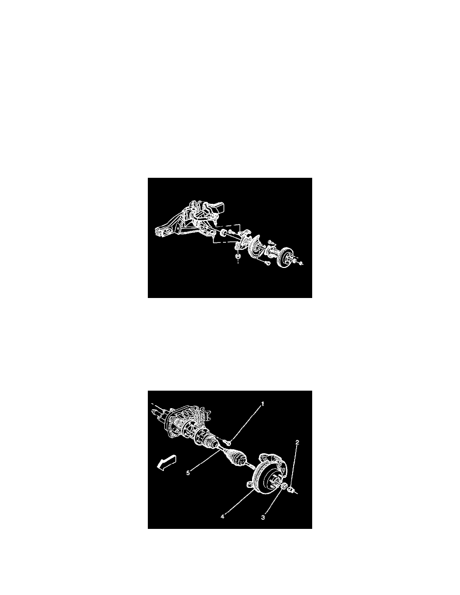
12. Install the halfshaft assembly (5).
13. Install the lower shock absorber bolt.
14. Install the stabilizer link.
15. Install the tire and wheel assembly.