
K 3500 Truck 4WD V8-6.6L DSL Turbo VIN 1 (2001)
8. An open in the class 2 serial data circuit between the DLC and the star connector will prevent the scan tool from communicating with any module.
This condition will not set a DTC.
9. The class 2 serial data circuit is shorted to voltage or ground. The condition may be due to the wiring or due to a malfunction in one of the
modules. When testing the wiring for a short, make sure there is not a module connected to the wire being tested. This test isolates the BCM class
2 serial data circuit.
11. This test isolates the PCM class 2 serial data circuit.
13. This test isolates the ATC class 2 serial data circuit.
15. This test isolates the EBCM class 2 serial data circuit.
17. This test isolates the SDM class 2 serial data circuit.
19. This test isolates the IPC class 2 serial data circuit.
21. This test isolates the SCM class 2 serial data circuit.
23. This test isolates the Automatic HVAC class 2 serial data circuit.
25. This test isolates the Automatic Transmission class 2 serial data circuit.
27. This test isolates the Driver Information Center (DIC) class 2 serial data circuit.
29. This test isolates the Mirror Memory Module class 2 serial data circuit.
31. This test isolates the Seat Memory Module class 2 serial data circuit.
33. This test isolates the OnStar(R)/Cellular Phone class 2 serial data circuit.
40. If there are no current DTCs that begin with a "U", the communication malfunction has been repaired.
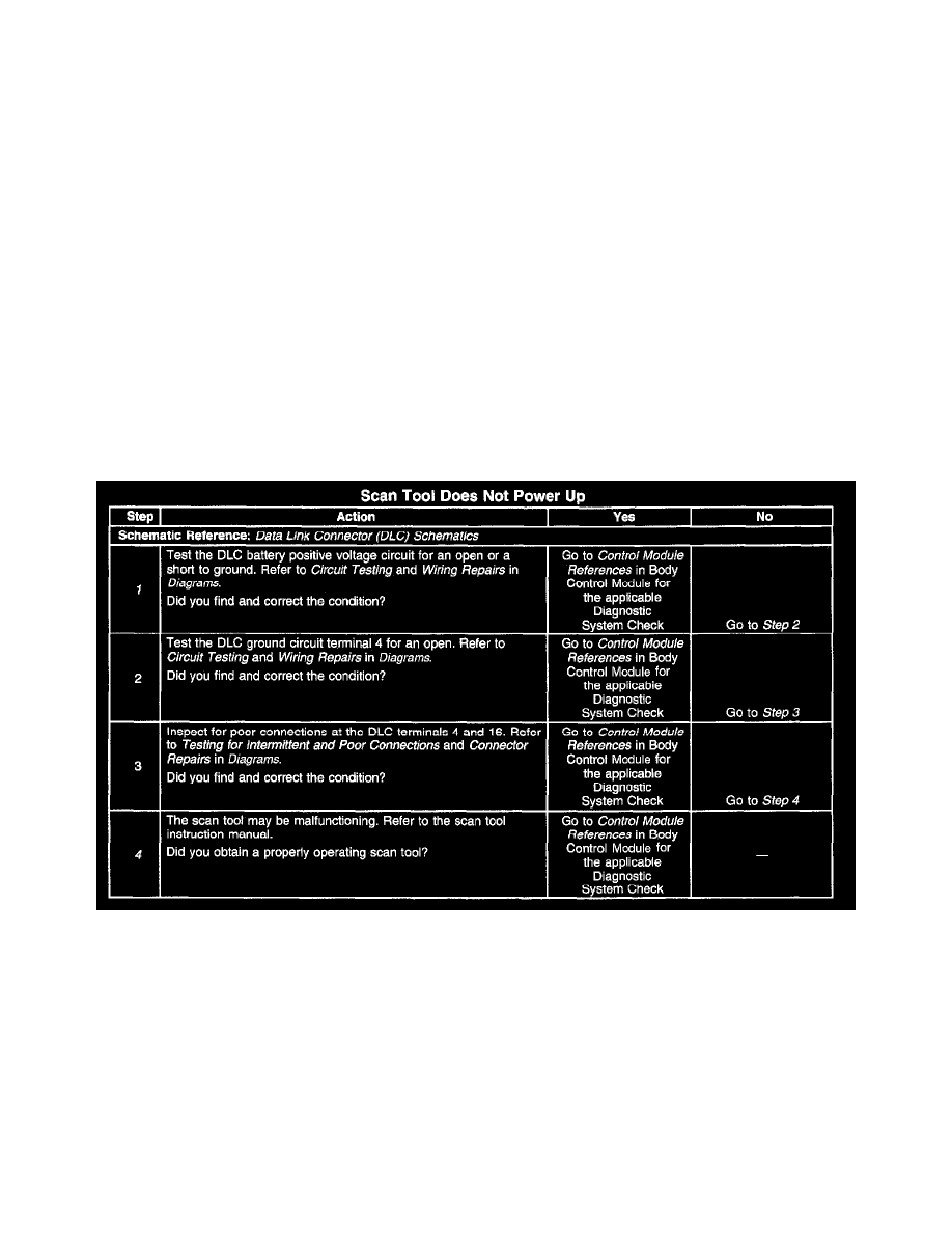
Scan Tool Does Not Power Up
CIRCUIT DESCRIPTION
The DLC provides battery positive voltage to the scan tool at terminal 16, and ground at terminal 4. The DLC provides the class 2 serial data signal at
terminal 2 and signal ground at terminal 5. The scan tool will power up with the ignition OFF.
TEST DESCRIPTION
Steps 1-4
Step numbers below refer to the same step numbers in the Diagnostic Table
1. The CIGAR fuse supplies power to the DLC terminal 16.
4. The DLC battery positive voltage and ground circuits are functioning. The malfunction is within the scan tool.