
K 3500 Truck 4WD V8-6.6L DSL Turbo VIN 1 (2001)
Circuit Protection Fuses
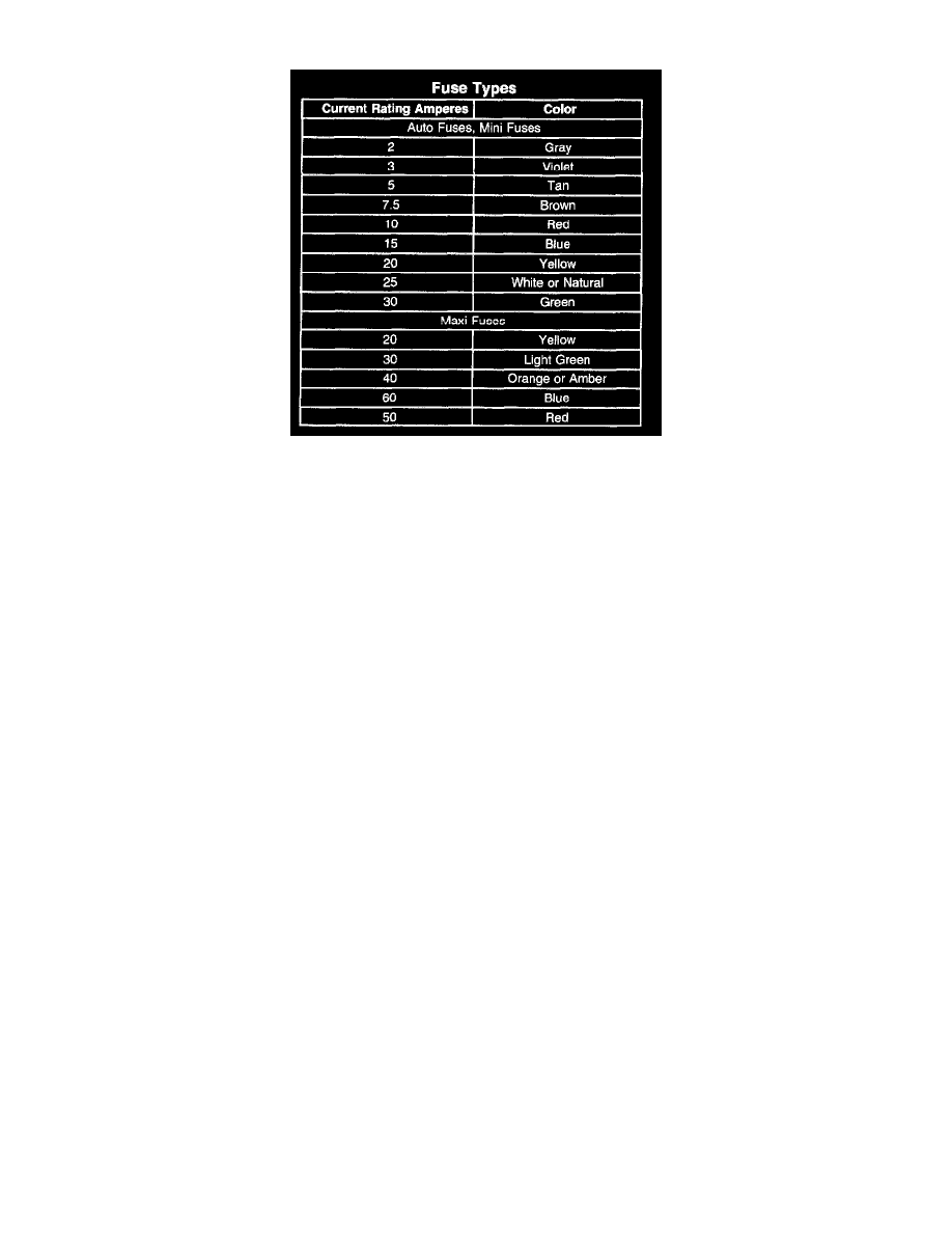
Fuse Types
The fuse is the most common method of an automotive wiring circuit protection. Whenever there is an excessive amount of current flowing through a
circuit the fusible element will melt and create an open or incomplete circuit. Fuses are an one time protection device and must be replaced each time the
circuit is overloaded. To determine if a fuse is open, remove the suspected fuse and examine the element in the fuse for an open (break). If not broken,
also check for continuity using a J 39200 DMM or a continuity tester. If the element is open or continuity is suspect, replace the fuse with one of equal
current rating.
Fusible Links
Fusible link is wire designed to melt and break continuity when excessive current is applied. It is often located between or near the battery and starter or
electrical center. Use a continuity tester or a J 39200 DMM at each end of the wire containing the fusible link in order to determine if it is broken. If
broken, it must be replaced with fusible link of the same gage size.
Repairing a Fusible Link
IMPORTANT: Fusible links cut longer than 225 mm (approximately 9 in) will not provide sufficient overload protection.
Refer to Splicing Copper Wire Using Splice Clips. See: Wiring Repairs/Splicing Copper Wire Using Splice Clips
Connector Test Adapters
NOTE: Do not insert test equipment probes into any connector or fuse block terminal. The diameter of the test probes will deform most terminals. A
deformed terminal can cause a poor connection, which can result in system failures. Always use the J 35616-A Connector Test Adapter Kit or the J
42675 Flat Wire Probe Adapter Kit in order to frontprobe terminals. Do not use paper clips or other substitutes as they can damage terminals and cause
incorrect measurements.
Digital Multimeter
NOTE: Refer to Test Probe Notice in Service Precautions.
IMPORTANT: Circuits which include any solid state control modules, such as the PCM, should only be tested with a 10 megohm or higher impedance
digital multimeter such as the J 39200.
The J 39200 instruction manual is a good source of information and should be read thoroughly upon receipt of the DMM as well as kept on hand for
future reference.
A DMM should be used instead of a test lamp in order to test for voltage in high impedance circuits. While a test lamp shows whether voltage is present,
a DMM indicates how much voltage is present.
The ohmmeter function on a DMM shows how much resistance exists between 2 points along a circuit. Low resistance in a circuit means good
continuity.
IMPORTANT: Disconnect the power feed from the suspect circuit when measuring resistance with a DMM. This prevents incorrect readings. DMMs
apply such a small voltage to measure resistance that the presence of voltages can upset a resistance reading.