
K 3500 Truck 4WD V8-6.6L DSL Turbo VIN 1 (2001)
Low Temperature Conditions
Depending on the nature of the fault condition, placing a fan in front of the vehicle while the vehicle is in the shade can have the desired effect.
If this is unsuccessful, use local cooling treatments such as ice or a venturi type nozzle (one that provides hot or cold air). This type of tool is capable
of producing air stream temperatures down to 0°F from one end and 160°F from the other. This is ideally suited for localized cooling needs.
Once the vehicle, component, or harness has been sufficiently cooled, manipulate the harness or components in an effort to duplicate the concern.
Measuring Frequency
NOTE: Refer to Test Probe Notice in Service Precautions.
The following procedure determines the frequency of a signal.
IMPORTANT: Connecting the DMM to the circuit before pressing the Hz button will allow the DMM to autorange to an appropriate range.
1. Apply power to the circuit.
2. Set the rotary dial of the DMM to the V (AC) position.
3. Connect the positive lead of the DMM to the circuit to be tested.
4. Connect the negative lead of the DMM to a good ground.
5. Press the Hz button on the DMM.
6. The DMM will display the frequency measured.
Measuring Voltage
NOTE: Refer to Test Probe Notice in Service Precautions.
The following procedure measures the voltage at a selected point in a circuit.
1. Disconnect the electrical harness connector for the circuit being tested, if necessary.
2. Enable the circuit and/or system being tested. Use the following methods:
-
Turn ON the ignition, with the engine OFF.
-
Turn ON the engine.
-
Turn ON the circuit and/or system with a scan tool in Output Controls.
-
Turn ON the switch for the circuit and/or system being tested.
3. Select the V (AC) or V (DC) position on the DMM.
4. Connect the positive lead of the DMM to the point of the circuit to be tested.
5. Connect the negative lead of the DMM to a good ground.
6. The DMM displays the voltage measured at that point.
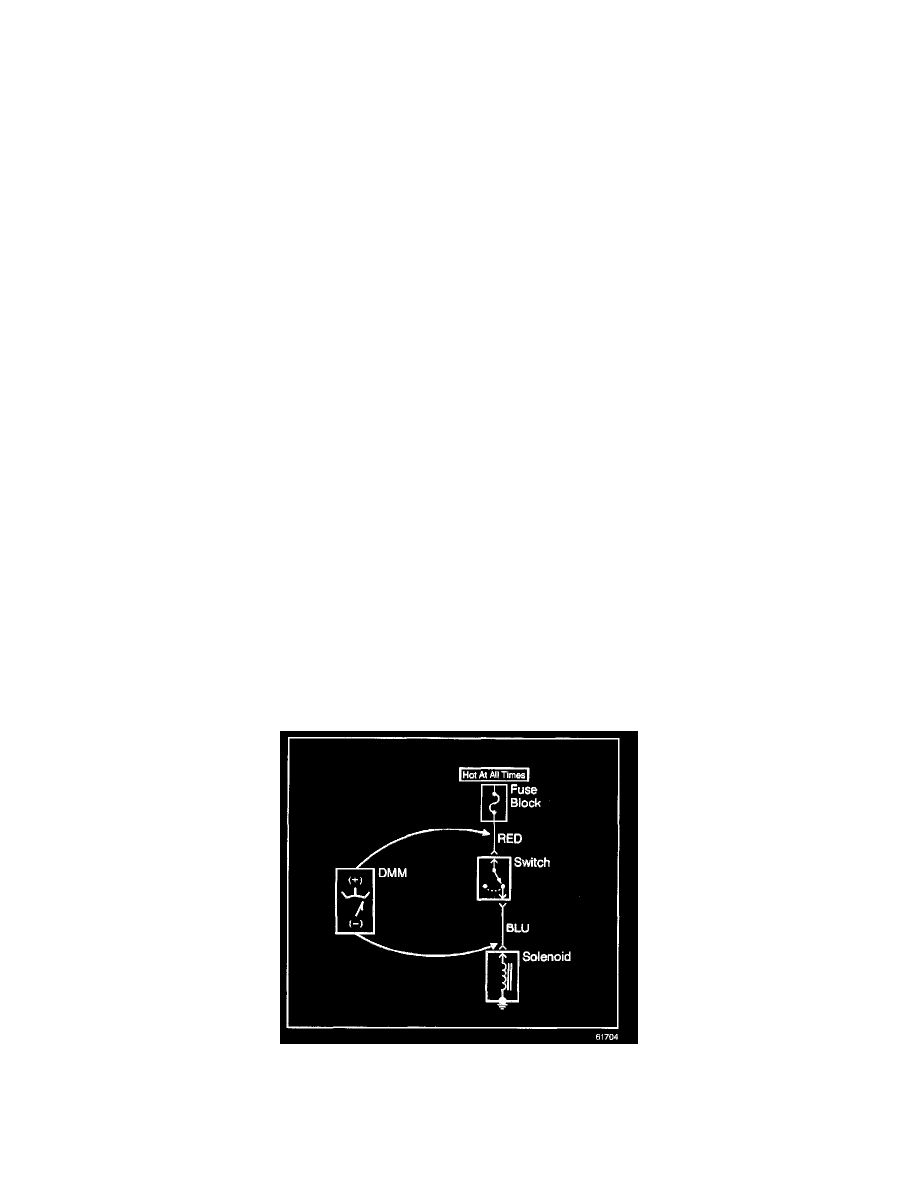
Measuring Voltage Drop
NOTE: Refer to Test Probe Notice in Service Precautions.
The following procedure determines the difference in voltage potential between 2 points.
1. Set the rotary dial of the DMM to the V (DC) position.
2. Connect the positive lead of the DMM to 1 point of the circuit to be tested.
3. Connect the negative lead of the DMM to the other point of the circuit.
4. Operate the circuit.
5. The DMM displays the difference in voltage between the 2 points.