
K 3500 Truck 4WD V8-6.6L DSL Turbo VIN 1 (2001)
^
An alignment mark (3) on the flush rotor flange cuff (4) for installation
^
A foam ring (1)
25. Remove the connector from the sensor.
26. Remove the sensor from the adapter and bearing assembly.
27. To install the sensor, proceed to step 21 in the installation section.
INSTALLATION PROCEDURE
IMPORTANT: If reusing the existing sensor, no centering of the sensor is required.
1. If installing a new sensor, it will come with a pin installed in the sensor. Do not remove the pin until the sensor is seated.
2. From the technicians point of view, the FRONT of the sensor (1) connector will be on your right. From the technicians point of view, the BACK of
the sensor (2) connector will be on your left.
3. Looking at the FRONT of the sensor, align the sensor with the steering shaft and install into the adapter and bearing assembly.
4. Install the connector to the sensor.
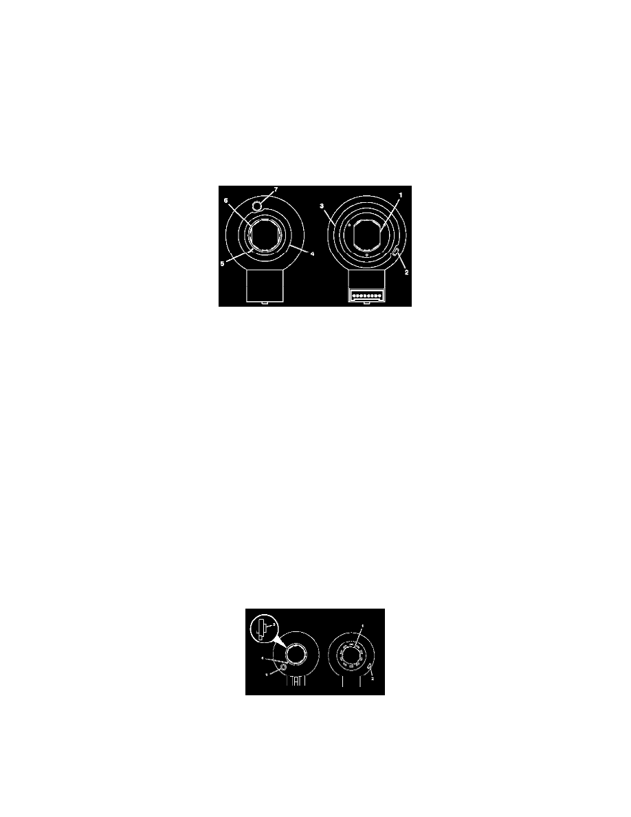
5. From the technicians point of view, the FRONT of the sensor will have:
^
A foam ring (4)
^
A pin hole (7) for the centering pin (note location of the pin hole)
^
A flushed rotor flange cuff (6)
^
An alignment mark (5) for installation
6. From the technicians point of view, the BACK of the sensor will have:
^
Double D flats (1)
^
A foam ring (3)
^
An alignment tab (2) for installing into the adapter and bearing assembly.
^
A view of the inside of the connector
IMPORTANT: If reusing the existing sensor, you must align the marks on the flush rotor flange cuff before installation. The alignment mark
must stay aligned until the sensor is seated into the adapter and bearing assembly.
IMPORTANT: If installing a new sensor, it will come with a pin installed in the sensor. Do not remove the pin until the sensor is seated. If the
new sensor did not come with a pin installed, you must reorder a new sensor.
7. Looking at the FRONT of the sensor, align the sensor with the steering shaft and install into the adapter and bearing assembly.
8. Install the connector to the sensor.
9. From the technicians point of view, the FRONT of the sensor will have:
^
A pin hole (3) for the centering pin (note location of the pin hole)
^
A raised rotor flange cuff (5)
^
An alignment mark (4) for installation
10. From the technicians point of view, the BACK of the sensor will have:
^
Double D flats (1)