
K 3500 Truck 4WD V8-6.6L DSL Turbo VIN 1 (2001)
Control Arm: Service and Repair
Front Lower
-
Tools Required
-
J 43631 Ball Joint Separator
Removal Procedure
1. Raise and support the vehicle. Refer to Vehicle Lifting.
2. Remove the tire and wheel. Refer to Tire and Wheel Removal and Installation.
3. Disconnect the Real Time Damping (RTD) link rod from the sensor (if equipped). Refer to Front Position Sensor Link Assembly Replacement -
Electronic Suspension in Real Time Damping.
4. Remove the stabilizer shaft links from the lower control arm. Refer to Stabilizer Shaft Replacement.
5. Remove the shock absorber lower nut and the bolt. Refer to Shock Absorber Replacement.
6. Remove the torsion bars. Refer to Torsion Bar Replacement.
7. Remove the wheel drive shaft. Refer to Wheel Drive Shaft Replacement.
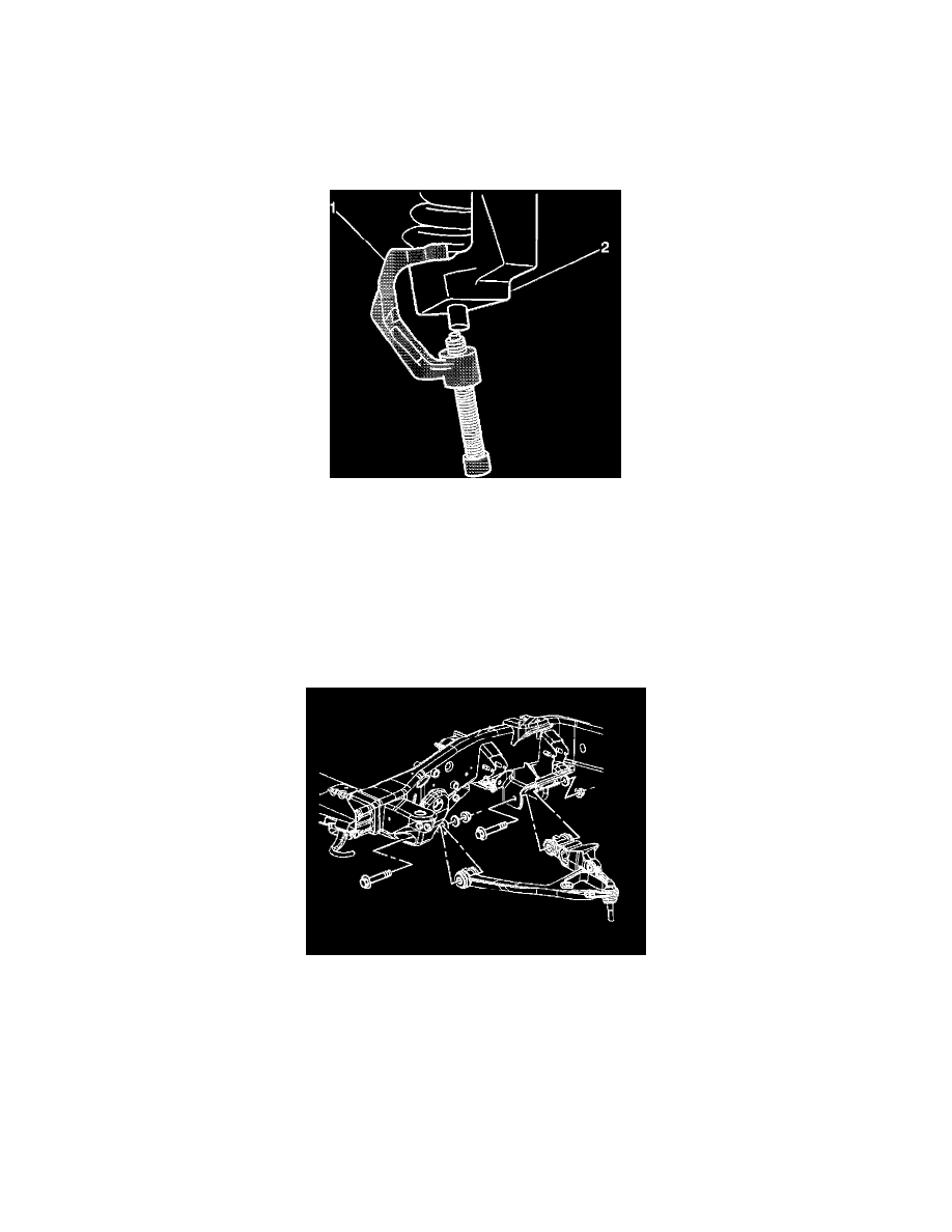
8. Remove the lower ball joint stud nut.
9. Disconnect the lower ball joint stud from the steering knuckle using J 43631(1).
10. Remove the lower control arm nuts and the washers (15 Series).
11. Remove the lower control arm bolts.