
K Yukon/Denali 4WD V8-5.7L VIN R (2000)
10. Ensure that the stake size is only one-half the area of the punch tip. Ensure that the stake is only approximately 0.28-0.35 mm (0.010-0.015 in)
deep.
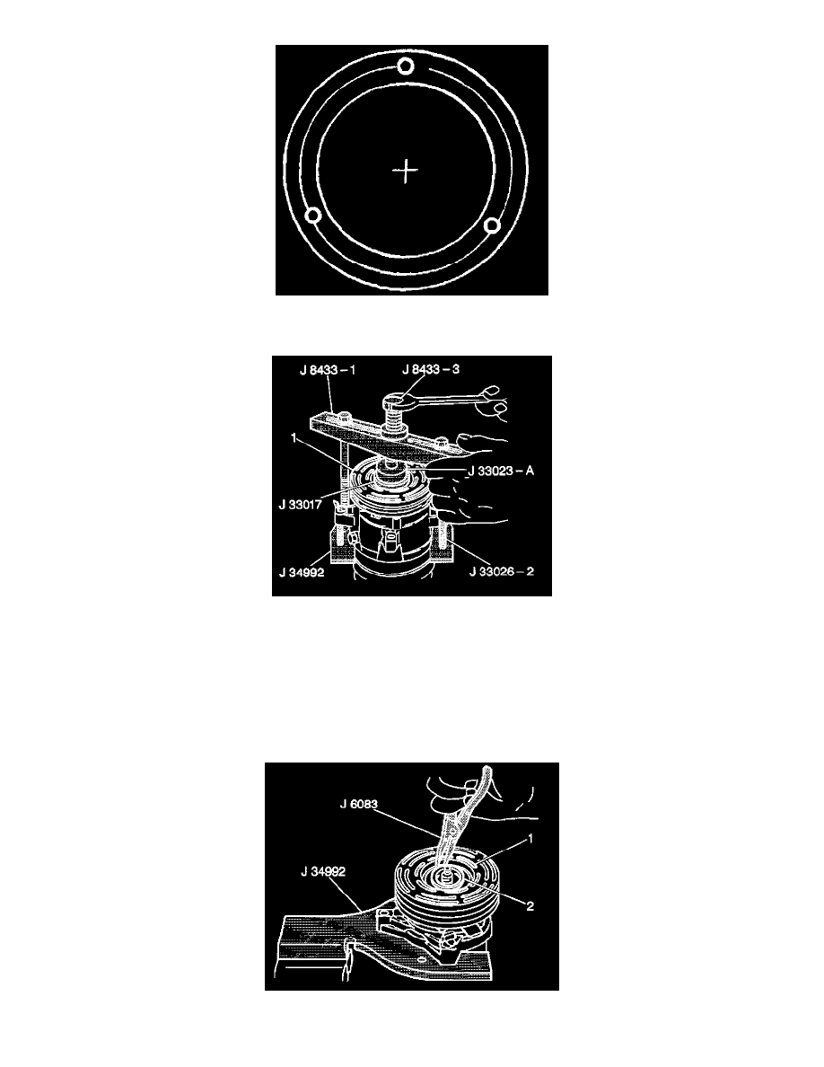
11. With the compressor mounted to the J 41790, position the pulley rotor (1) and bearing assembly on the front head.
12. Position the J 33017 and the J 33023-A directly over the inner race of the bearing.
13. Position the J 8433-1 on the J 33023-A.
14. Assemble the two bolts and washers through the puller bar slots.
15. Thread the bolts into the J 41790. Ensure that the thread of the through bolts engages the full thickness of the J 41790.
16. Tighten the center screw in the J 8433-1 in order to force the pulley rotor and bearing assembly (1) onto the compressor front head.
If the J 33017 slips off direct in-line contact with the inner race and bearing, Perform the following steps:
16.1. Loosen the J 8433-3.
16.2. Realign the installer and the pilot in order to ensure that the J 33017 properly clears the front head.
17. Use the J 6083 in order to install the following components: