
K Yukon/Denali 4WD V8-5.7L VIN R (2000)
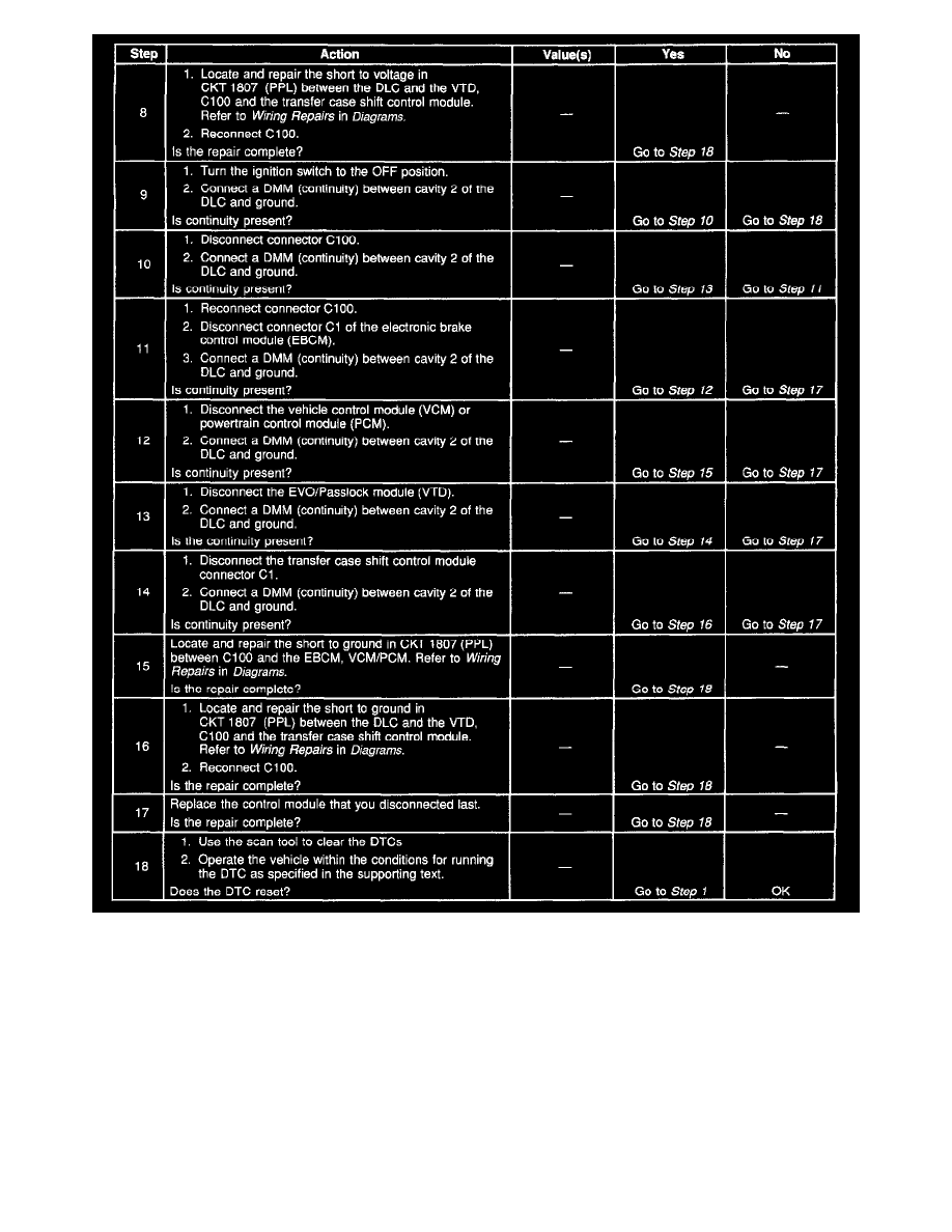
Diagnostic Chart (Part 2 Of 2)
CIRCUIT DESCRIPTION
Modules connected to the class 2 serial data circuit monitor for serial data communications during normal vehicle operation. Operating information
and commands are exchanged among the modules. Connecting a scan tool to the DLC allows communication with the modules for diagnostic
purposes. Diagnostic trouble codes (DTCs) may be set due to this symptom and during this diagnostic procedure. Complete the diagnostic procedure
in order to ensure all the DTCs are diagnosed and cleared from memory.
DIAGNOSTIC AIDS
^
The VCM (Gas) and PCM (Diesel) detects that the ignition is ON and sends the appropriate power mode message to the other modules. Therefore,
the VCM (Gas) and PCM (Diesel) must be connected to the DLC for any other module to communicate with the scan tool.
^
When the class 2 serial data circuit is shorted to ground, U1300 or U1305 will be set. Refer to DTC U1300 Class 2 Data Link Low or DTC U1300
Class 2 Data Link Low.
^
When the class 2 serial data circuit is shorted to B+ U1301 or U1305 will be set. Refer to DTC U1301 Class 2 Data Link High or DTC U1301
Class 2 Data Link High.