
K Yukon/Denali 4WD V8-5.7L VIN R (2000)
Alignment: Service and Repair
Frame Bracket Knock Out Removal
Removal Procedure
Tools Required
-
J 38794 Knockout Removal Tool
1. Raise the vehicle. Support the vehicle with suitable safety stands. Refer to Vehicle Lifting.
Important: The jack or the jack stand must remain under the lower control arm during the removal and the installation procedure in order to retain
the lower control arm position.
2. Support the lower control arms with a jack or the jack stands.
3. Remove the tire and the wheel assembly.
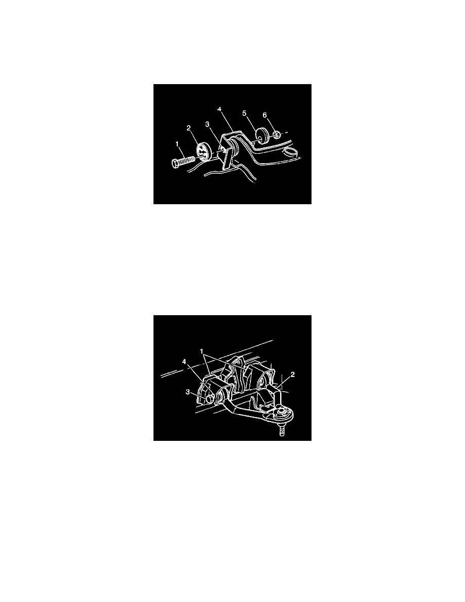
4. Remove the following parts from the upper control arm bracket (2):
-
The nuts
-
The cams (4)
-
The bolts (3)
5. Lift the upper control arm (2) up and to the side in order to gain access to the inner portion of the frame bracket.
Notice: Do not subject the tool to more than 100 Nm (75 ft. lbs.) torque. Exceeding the recommended torque may damage the tool and/or the
bracket.
6. Use the J 38794 in order to remove the frame bracket knockout as follows:
-
Do not distort the frame bracket when removing the knockout.
-
Apply extreme pressure lubricant to the threads of the T-bolt.
-
Insert the bolt through the knockout hole in the bracket support.
-
Install the bridge onto the T-bolt.
The forward bracket requires the bridge to be installed between the legs of the bracket due to access problems.
-
Assemble the following parts in order:
6.1.
The bridge
6.2.
The bearing with the chamfered side out
6.3.
The washer