
K Yukon/Denali 4WD V8-6.5L DSL Turbo VIN S (1999)
Notice: Do not subject the tool to more than 100 Nm (75 ft. lbs.) torque. Exceeding the recommended torque may damage the tool and/or the
bracket.
-
An open end wrench or adjustable wrench may be needed in order to prevent the T-bolt from losing the horizontal alignment with the
knockout.
-
If the torque limit on the T-bolt is met and the knockout does not break free, use a die grinder of appropriate size.
Using the stamped outline as a guide, remove the knockout.
Remove the wax coating in the knockout area in order to make the perforation lines more visible.
-
If the outline is not visible, use the T-bolt head installed horizontally, as a template, and scribe the frame bracket.
-
Repeat the procedure on the other upper control arm frame bracket.
INSTALLATION PROCEDURE
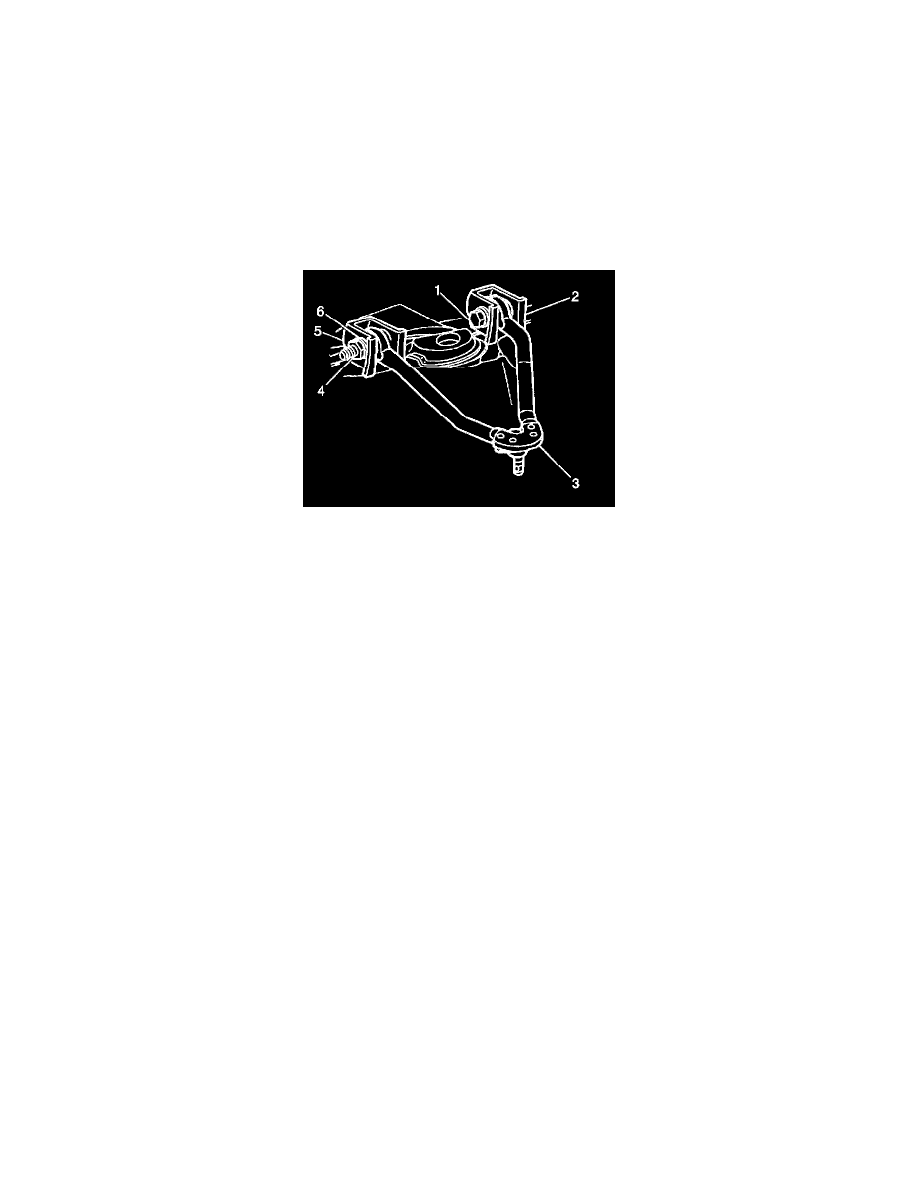
1. Install the upper control arm (2) into the frame brackets.
2. Install the bolts and the cams (4) through the frame brackets and through the control arm (2).
3. Install the cams (4) and the nuts.
Install the cams with the radius toward the frame brackets.
4. Partially tighten the nut.
5. Install the tire and the front wheel assemblies.
6. Install the alignment machine heads.
7. Adjust the caster and the camber to the correct specifications by rotating the bolt head installed through the adjuster cam.
7.1. Tighten the front upper control arm nuts to 190 Nm (140 ft. lbs.).
7.2. Tighten the rear upper control arm nuts to 190 Nm (140 ft. lbs.).
Notice: Refer to Fastener Notice in Service Precautions.
Important: Verify alignment specifications before proceeding. Refer to Wheel Alignment Specifications.
8. Set the steering wheel on center with the wheels straight.
9. Loosen the adjuster sleeve nuts.
10. Adjust the toe-in.
-
Tighten the tie rod adjuster sleeve nuts to 19 Nm (14 ft. lbs.).
11. Ensure that the clamps are properly positioned.
12. Recheck the alignment specifications.
13. Lower the vehicle.