
S15/T15 2WD Jimmy V6-262 4.3L (1991)
Brake Warning Indicator: Description and Operation
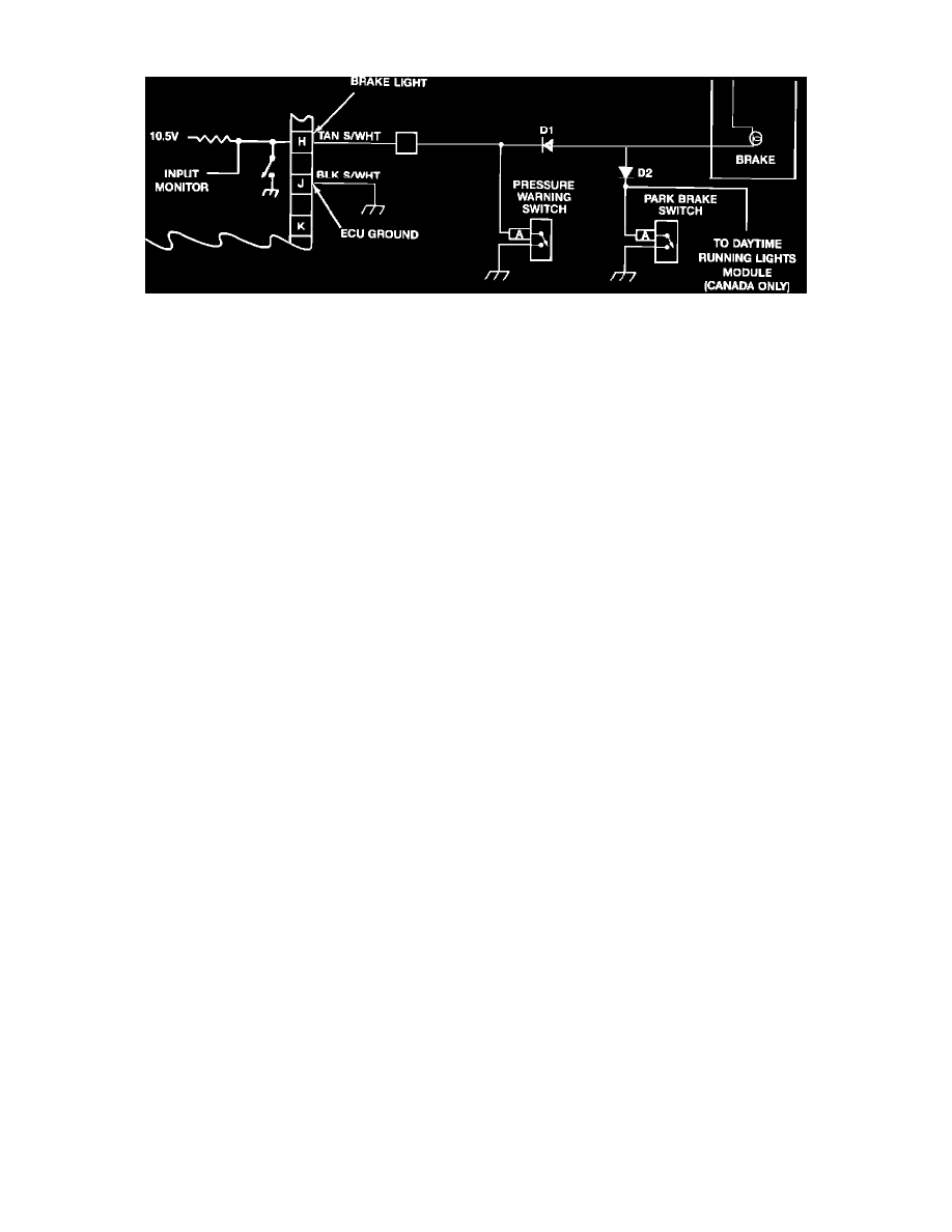
Brake Light Circuit
The vehicle instrument cluster has a red "Brake" warning light to alert the driver to the following conditions:
^
Parking brake applied
^
A hydraulic failure in either the front or rear channel
^
An anti-lock light circuit problem exists
An ignition switch-controlled circuit provides power to the "Brake" light in the vehicle instrument cluster. There are three parallel paths to chassis
ground to complete the circuit:
^
Through the parking brake switch contacts
^
Through the combination valve differential pressure switch contacts
^
Through the ECU circuitry
The ECU completes the "Brake" light circuit for several reasons:
^
To conduct a "Brake" light circuit check at the beginning of each ignition cycle
^
To alert the driver of a 4WAL malfunction related to the foundation brakes
The ECU also monitors the "Brake" light circuit. An isolation diode (Dl) allows an ECU monitor circuit to be grounded by the differential pressure
switch, which also provides a complete circuit for the "Brake" light. As a diagnostic action to this condition, the ECU will adjust its antilock control
programming.
The operation of the park brake switch does not affect the ECU monitor circuit for the "Brake" light, due to the blocking action of D1. Another isolation
diode (D2) prevents the park brake switch from providing an input to the daytime running lights module (used in Canadian vehicles).
The ECU checks the "Brake" light circuit at the beginning of each ignition cycle. If the ECU monitors low voltage at terminal H before it attempts to
ground the light circuit, it determines that a short exists. Diagnostic action for this detected condition includes storing a trouble Code 88.