
S15/T15 2WD Jimmy V6-262 4.3L (1991)
this condition, the procedure below should be followed:
See Figure 16:
1. Loosen bolts (90) attaching the axle tube bracket (5) to the frame bracket (6).
2. Tighten nuts (94) to 75 N-m (55 lbs.ft.). This should cause the axle assembly to move toward the drivers side approximately 1/8" to 1/4." If the axle
does not move it may pried toward the drivers side with a bar. Position bar against the frame and the end of the shaft (1).
3. Tighten bolts (90) to 75 N-m (55 lbs.ft.).
SEAL REPLACEMENT After checking the shock absorber installation and front axle location, smaller profile tripot seals may be installed. These
smaller seals can be identified by their visibly smaller profile and by the number 26027961 which is molded onto the seal.
Required Tools:
J 28733 Axle Remover
J 24319-01 Tie Rod Puller
J 8059 Snap Ring Pliers
J 35910 Seal Clamp Tool
J 34026 Ball Joint Separator
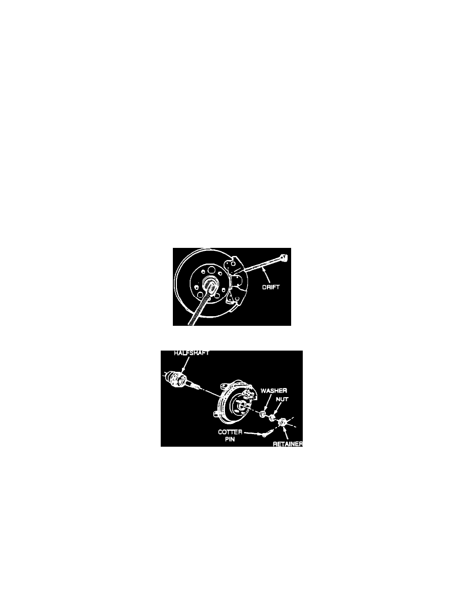
Figure 1 - Prevent Shaft From Turning
Figure 2 - Hub Nut and Washer Removal
Drive Axle Removal
1. Raise vehicle and support it with suitable safe ty stands.
2. Remove the wheel and tire assembly.
3. Insert a drift or large screwdriver through brake caliper into one of the brake rotor vanes to prevent halfshaft from turning (Figure 1).
4. Remove cotter pin, retainer, hub nut, and washer (Figure 2).