
S15/T15 2WD Jimmy V6-262 4.3L VIN W CPI (1993)
Installing The Drive Plate
-
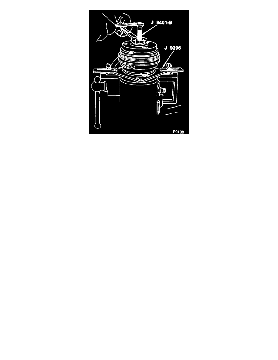
Install J 9401-A on the threaded end of the shaft.
-
Back off J 9401-A body to allow the center screw to be threaded against the end of the compressor shaft (39).
-
Hold the center screw with a wrench and tighten the hex portion of J 9401-A body while pressing the hub onto the shaft (39). After tightening
the body several turns, remove J 9401-A and check that the shaft key (36) is properly in place in the keyway.
-
Air gap between contact surfaces of the clutch plate and hub assembly (2) and the pulley (6) should be 0.56-1.34 mm (0.022-0.057 inch).
-
Remove J 9401-A.
Inspect
-
Position of the shaft (39) (even with or slightly above the clutch hub).
3. Shaft nut (1).
-
Use J 25030-A to hold the clutch plate and hub assembly (2).
Tighten
-
Shaft nut (1) to 27 N.m (20 ft.lbs.) with J 9399-A.
-
Hand spin the pulley (6) to check for free rotation.
Clutch Rotor and Bearing Assembly