
S15/T15 2WD Jimmy V6-262 4.3L VIN Z (1992)
-
HVAC Actuator
-
Inflatable Restraint Sensing and Diagnostic Module (SDM)
-
Any AIR BAG module
-
Seatbelt Lap Anchor Pretensioner
-
Seatbelt Retractor Pretensioner
-
An SIR system connection or connector condition resulting in the following DTCs being set: B0015, B0016, B0019, B0020, B0022, or B0023
-
Powertrain Control Module (PCM)
-
Remote Control Door Lock Receiver (RCDLR)
-
Transmission Control Module (TCM)
Correction
Important
DO NOT replace the control module, wiring or component for the following conditions:
-
The condition is intermittent and cannot be duplicated.
-
The condition is present and by disconnecting and reconnecting the connector the condition can no longer be duplicated.
Use the following procedure to correct the conditions listed above.
1. Install a scan tool and perform the Diagnostic System Check - Vehicle. Retrieve and record any existing history or current DTCs from all of the
control modules (refer to SI).
‹› If any DTC(s) are set, refer to Diagnostic Trouble Code (DTC) List - Vehicle to identify the connector(s) of the control module/component
which may be causing the condition (refer to SI).
‹› If DTCs are not set, refer to Symptoms - Vehicle to identify the connector(s) of the control module/component which may be causing the
condition (refer to SI).
2. When identified, use the appropriate DTC Diagnostics, Symptoms, Schematics, Component Connector End Views and Component Locator
documents to locate and disconnect the affected harness connector(s) which are causing the condition.
Note
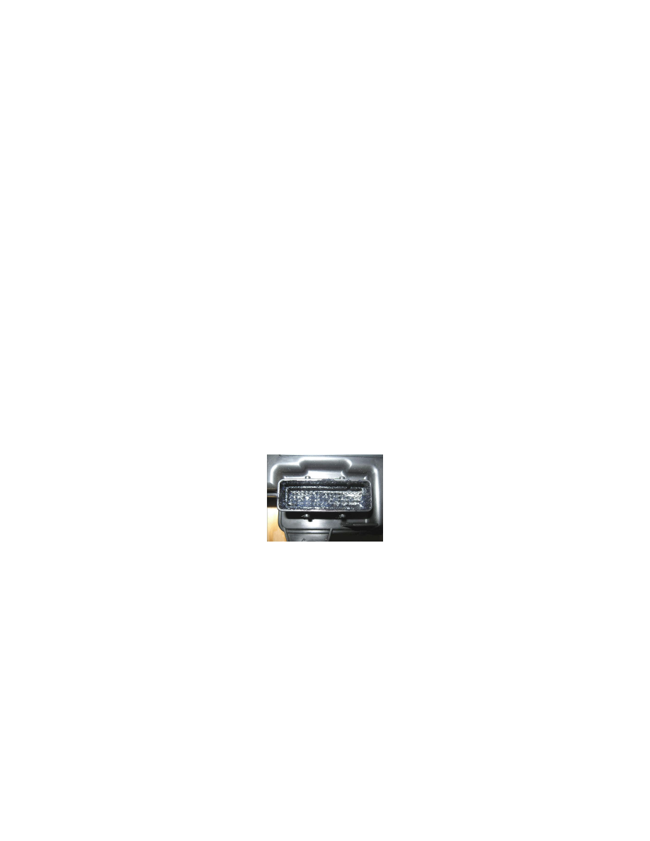
Fretting corrosion looks like little dark smudges on electrical terminals and appear where the actual electrical contact is being made. In less severe
cases it may be unable to be seen or identified without the use of a magnifying glass.
Important
DO NOT apply an excessive amount of dielectric lubricant to the connectors as shown, as hydrolock may result when attempting to mate the
connectors. Use ONLY a clean nylon brush that is dedicated to the repair of the conditions in this bulletin.
3. With a one-inch nylon bristle brush, apply dielectric lubricant to both the module/component side and the harness side of the affected connector(s).
4. Reconnect the affected connector(s) and wipe away any excess lubricant that may be present.
5. Attempt to duplicate the condition by using the following information:
-
DTC Diagnostic Procedure
-
Circuit/System Description
-
Conditions for Running the DTC
-
Conditions for Setting the DTC
-
Diagnostic Aids
-
Circuit/System Verification
‹› If the condition cannot be duplicated, the repair is complete.
‹› If the condition can be duplicated, then follow the appropriate DTC, Symptom or Circuit/System Testing procedure (refer to SI).
Repair Order Documentation