
S15/T15 2WD P/U V6-262 4.3L (1988)
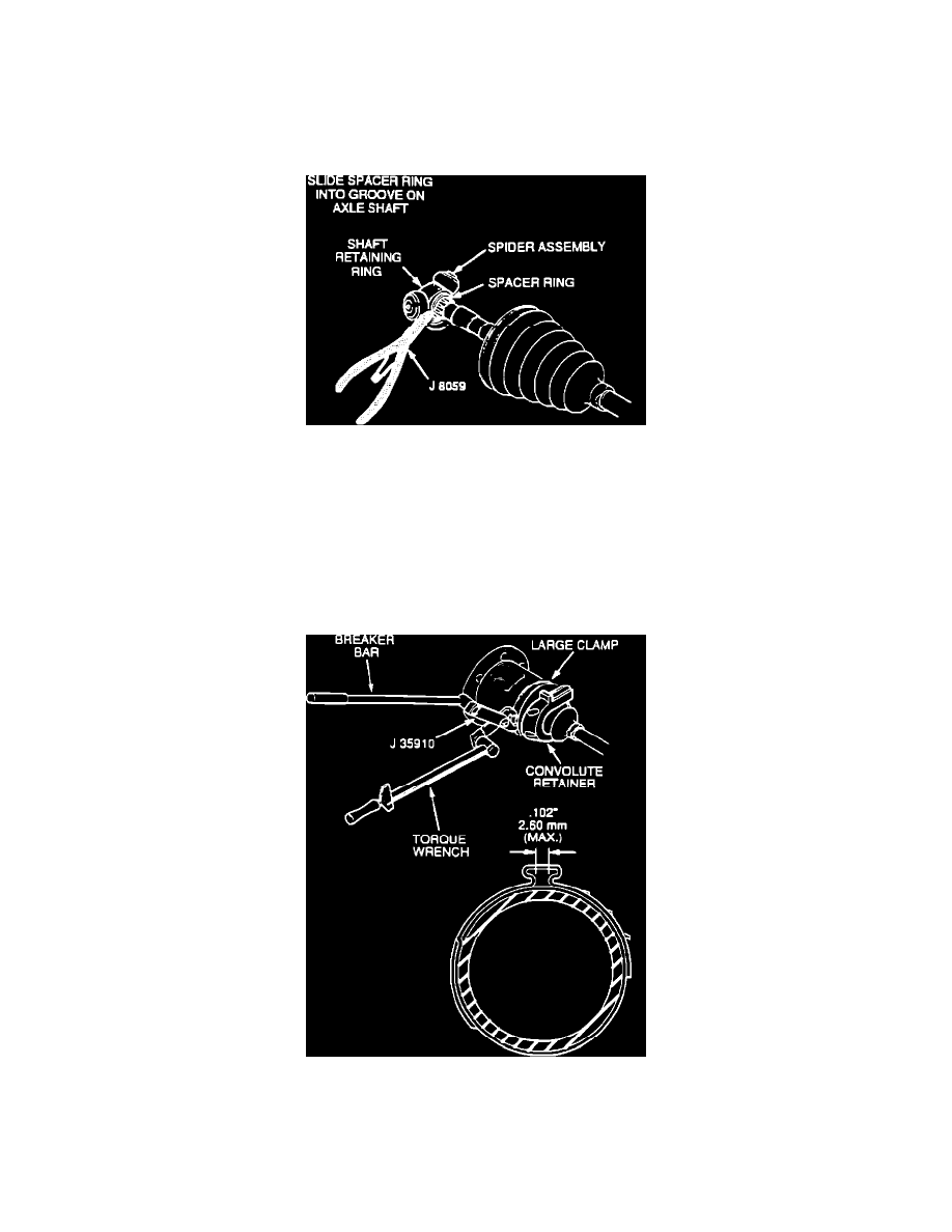
Figure 13 - Proper Inboard Stroke Positioning
9.
Install convolute retainer over seal capturing four convolutes (Figure 13).
Important
Joint must be assembled with convolute retainer in position as shown in Figure 13. Seal damage will result if joint is not assembled to dimension shown.
Figure 14 - Spider Assembly Installation
10. Install spacer ring and spider assembly (with counterbore towards end of shaft) on the shaft far enough to allow installation of the retaining ring at
the end of the axle shaft (Figure 14).
11. Install the retaining ring and push the spider assembly toward the end of the shaft until retaining ring is covered by the spider assembly counterbore.
Install the spacer ring and make sure it is seated in its groove.
12. Pack the seal and housing with grease supplied in the kit, (the amount of grease supplied in this kit has been premeasured for this application), place
the large metal clamp on the seal, then place the housing over the spider assembly and snap the seal onto the housing.
Figure 15 - Large Retaining Clamp Installation
13.
Secure the large metal clamp and seal to the housing with tool J35910, breaker bar, and torque wrench. Torque the large clamp to 176 N-m (130
lbs.ft.). Check clamp ear gap dimension (Figure 15).
Drive Axle Installation