
S15/T15 4WD Jimmy V6-173 2.8L (1988)
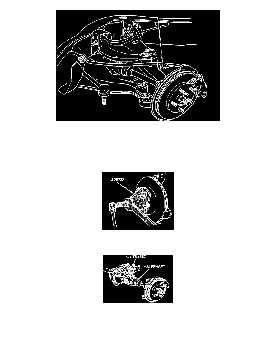
Figure 9 - Connecting the Upper Ball Joint
17.
Tip the knuckle out and toward the rear of the vehicle. Suspend the knuckle to prevent straining the brake line (Figure 9).
Important
Cover the shock mounting bracket and the ball stud on the lower control arm with a shop towel to prevent possible drive axle seal damage during
removal and installation.
Figure 8 - Splined Shank and Knuckle Separation
18.
Install J28733 on brake rotor and separate outer C/V joint splined shank from knuckle hub (Figure 8).
Figure 3 - Inboard Flange Bolt Removal
19.
Remove six bolts (loosened earlier) from inboard joint flange (Figure 3).
20.
Support inboard end of drive axle. Free splined shank from hub and remove drive axle assembly from vehicle.
Important