
S15/T15 4WD Jimmy V6-173 2.8L (1988)
Wiring Diagram For Chart C-8 - Transmission Converter Clutch (TCC) (Electrical Diagnosis)
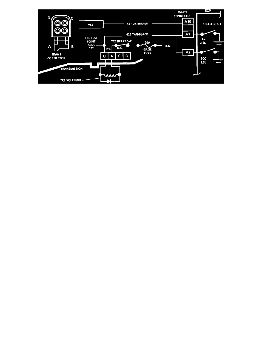
CHART C-8 - TRANSMISSION CONVERTER CLUTCH
Circuit Description:
The purpose of the automatic transmission converter clutch feature is to eliminate the power loss of the torque converter stage when the vehicle is in a
cruise condition. This allows the convenience of the automatic transmission and the fuel economy of a manual transmission. Fused battery ignition is
supplied to the TCC solenoid through the TCC brake switch. The ECM will engage TCC by grounding CKT 422 to energize the solenoid.
TCC will engage when:
-
Vehicle speed above 24 mph (39 km/h).
-
Engine at normal operating temperature (above 65~C) (149~F).
-
Throttle position sensor output not changing, indicating a steady road speed.
-
Brake switch closed.
-
3rd or 4th gears.
Test Description: Numbers below refer to circled numbers on the diagnostic chart.
1.
Checks continuity through brake switch and TCC solenoid.
2.
Checks capability of ECM to energize solenoid. Grounding the diagnostic connector should energize the relay and cause the light to go out.
3.
This test by-passes the TCC solenoid and checks for an open or short in CKT 422.
Diagnostic Aids:
Solenoid coil resistance must measure more than 20 ohms. Less resistance will cause early failure of the ECM "Driver", Refer to ECM QDR check.
Using an ohm meter, check the solenoid coil resistance of all ECM controlled solenoids and relays, before installing a replacement ECM. Replace any
solenoid, or relay, that measures less than 20 ohms resistance.