
S15/T15 4WD Jimmy V6-262 4.3L VIN W CPI (1993)
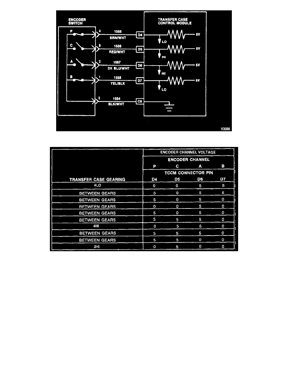
Fig 2, Electric Shift Encoder Switch Schematic
Fig 3, Encoder Switch Channel Signals And Positions
OPERATION
The four-channel encoder switch indicates the current transfer case mode and range to the Transfer Case Control Module (TCCM). The encoder
switch is located inside the encoder itself and is not serviceable. The TCCM reads the status of the four channels to determine the range and mode
in which the transfer case is operating or whether the transfer case is shifting between modes and/or ranges. The encoder assembly is composed of
an inner ground ring in contact with a three-leg wiper arm. The three legs of the wiper, spaced 120 degrees apart, make contact with the conductive
areas of the four channels. When any leg of the wiper arm is in contact with the conductive area of any channel, a path to ground is provided to the
inner ground ring. A schematic of the encoder switch is shown in Figure 2. The channel signals in various transfer case operating modes and
ranges are shown in Figure 3. Any combination of signals not listed in Figure 3 are considered invalid by the TCCM.
Encoder Switch Channel Positions
These voltage readings can be obtained by back-probing either the TCCM connector pins or the transfer case connector pins. For TCCM pin
numbers and encoder channels, refer to Figure 2.
Diagnostic Enable Input