
S15/T15 4WD Jimmy V6-262 4.3L VIN Z (1992)
When replacing the Transfer case encoder assembly (P/N 15636696) on 1992-93 electric shift transfer cases (New Process 233), the correct service
procedures must be followed. Failure to install the encoder motor assembly correctly may result in contamination and corrosion of the encoder and its
electrical components.
It is very important that the mounting surfaces be clean and free of debris. The sealing O-ring must be correctly in place on the encoder pilot to ensure a
positive seal (Figure 1).
SERVICE PROCEDURE
To remove the encoder motor assembly:
1.
Disconnect the negative battery cable.
2.
Raise the vehicle and support with suitable safety stands.
3.
Disconnect the electrical connection to the transfer case encoder.
4.
Remove the front propeller shaft.
5.
Remove the front output shaft yoke, section 7D, Figure 12 in the 1992 Sonoma and Jimmy Service Manual.
6.
Remove the encoder motor assembly by removing the (3) 8 mm hex bolts.
NOTE:
REMOVE ONLY THE 8 mm HEX NUTS AS SEVERE DAMAGE TO INTERNAL COMPONENTS OF THE ENCODER MOTOR ASSEMBLY
MAY RESULT IF THE TORX HEAD BOLTS ARE REMOVED. DO NOT REMOVE THE TORX HEAD BOLTS.
To install the encoder motor assembly:
1.
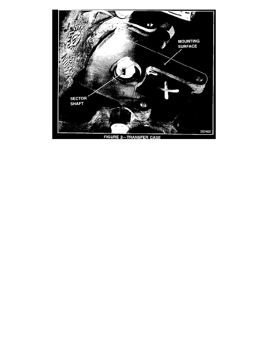
All mounting surfaces must be clean and free from burrs and debris (Figure 1 and 2).
2.
Set the sealing O-ring on the encoder motor pilot (Figure 1).
Note:
Check the alignment of the transfer case sector shaft with the drive sleeve in the encoder motor assembly. The transfer case should be in 4-High (The
flats on the sector shaft vertical for proper alignment Rotate the transfer case sector shaft for proper alignment if required.
3.
Install the encoder motor assembly. Torque the bolts to 18 N-m (13 lbs.ft.).