
S15/T15 4WD P/U V6-262 4.3L VIN W CPI (1992)
Electrical Connector - With Tier 1 Emissions
CONSTRUCTION
Positioned at the top of the Linear EGR assembly are 5 terminals:
1. A is the pulse width modulated negative signal from the PCM.
2. E is the positive from the ignition.
3. B, C and D are terminals from the control module for the integral pintle position sensor.
a. B is sensor ground.
b. C is sensor output.
c. D is +5 volts supply.
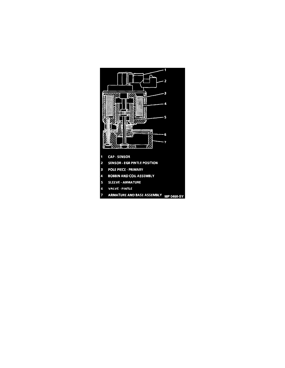
EGR Valve Subassemblies
OPERATION
The solenoid (bobbin and coil) assembly is energized by 12 volt current which enters the valve through an electrical connector (terminal E), then
flows through the solenoid assembly to the PCM and creates and electromagnetic field. This Field causes the armature assembly to be pulled
upward, lifting the pintle a variable amount off the base.
The exhaust gas then flows from the exhaust manifold (through the orifice) to the intake manifold. The height of the pintle is read by the pintle
position sensor, and the PCM closes the loop on desired position versus actual position read, changing the pulse width modulated command to the
solenoid accordingly, until the actual pintle position equals the desired pintle position.
This results in improved flow accuracy. In most EGR designs, the flow is "OPEN LOOP", in which the system has NO feedback mechanism to
monitor actual flow and then correct it.
The Linear EGR valve is unique in that the control module continuously monitors pintle height and continuously corrects it in order to obtain
accurate flow, making Linear EGR a " CLOSED LOOP" system.
When the solenoid is de-energized (PCM breaks the circuit), the pintle is seated against the orifice, blocking exhaust flow to the intake manifold.