
S15/T15 4WD P/U V6-262 4.3L VIN W CPI (1992)
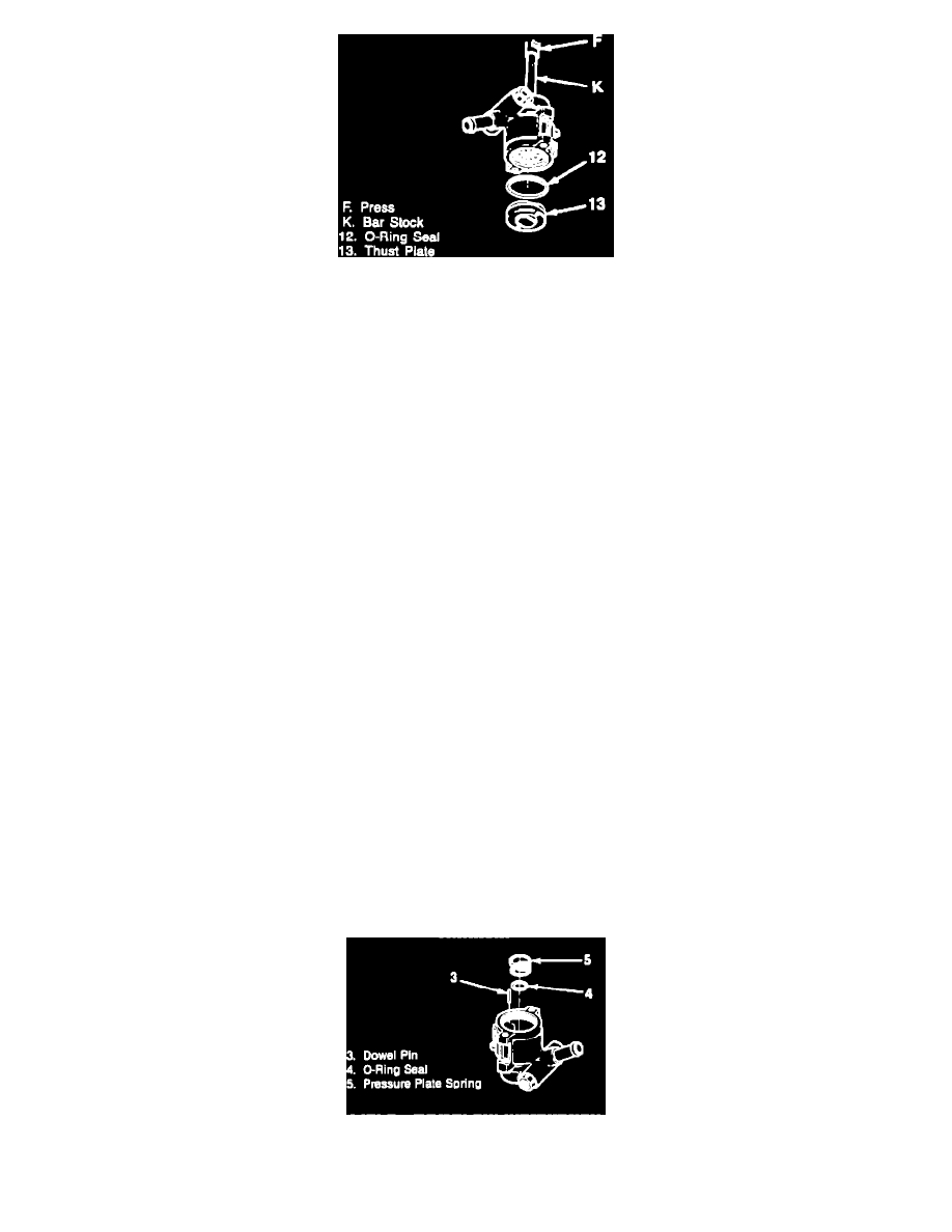
Fig. 8 Thrust plate removal
Prior to disassembly of the pump, remove filler cap and drain fluid. If broken components or foreign materials are found during disassembly, the
hydraulic system should be disassembled, inspected, cleaned and flushed before service is complete.
Refer to Fig. 1, for pump disassembly.
1.
Clean exterior of pump with solvent, then clamp front hub of pump into a soft jaw vise.
2.
Pry tab and slide retaining clip off of pump, Fig. 2.
3.
Remove reservoir, then return tube as follows:
a.
Assemble five 5/8 inch washers and a 9/16 inch-12 nut outside of tube, Fig. 3.
b.
Plug tube to prevent chips from entering, then insert a 9/16 X 12 tap into return tube and turn until tube is pulled out of housing, Fig. 3.
4.
Remove O-ring, fitting, O-ring seal, flow control valve and spring. Fig. 4.
5.
Using snap ring pliers, remove retaining ring. Note position of large lug in housing before removal. Fig. 5.
6.
Remove driveshaft and bearing, Fig. 6. Note and measure any clearance between collar and shaft. Press bearing from shaft using a support ring
under bearing.
7.
Remove driveshaft seal by prying seal loose with a screwdriver.
8.
Insert a punch into access hole, then pry retaining ring loose with a screwdriver, Fig. 7.
9.
Using a 5/16 inch piece of bar stock or a suitable brass drift, remove thrust plate, Fig. 8.
10.
Remove pump ring, rotor, vanes and dowel pins.
11.
Remove pressure plate and O-ring, then the spring, seal and remaining dowel pin.
12.
Using a suitable punch, remove sleeve assembly.
Inspection
1.
Clean all parts with solvent and blow dry.
2.
Inspect rotating components as follows:
a.
Vane tips for scoring or wear.
b.
Fit of vanes in rotor. Vanes must fit properly in slots without sticking or excessive play.
c.
Rotor slots for burrs and excessive wear at thrust faces.
d.
Inner surface of pump ring for scoring or wear.
e.
Thrust plate and pressure plate for wear on plate surfaces.
f.
If heavy wear is present, or parts are faulty, replace entire rotating group.
3.
Inspect bearing for rough or looseness and bearing seal for leakage, cracking or swelling.
4.
Check driveshaft and bearing bore for excessive burning or scoring.
5.
Control valve must move smoothly in the valve bore.
Assembly
Fig. 9 Dowel pin installation