
S15/T15 Jimmy 2WD V6-262 4.3L VIN Z (1994)
Before fully seating the assembly on the Front Head, be sure the clutch coil terminals are in the proper location in relation to the compressor and
that the three protrusions on the rear of the clutch coil align with the locator holes in the Front Head.
3. Install the rotor and bearing assembly retaining ring and reassemble the Clutch Plate and Hub assembly as described in "Compressor Clutch Plate
and Hub Assembly" Replacement procedure. Check to see that the clutch plate to clutch rotor air gap is 0.5-7.6mm (0.020-0.030").
Rotate the Pulley Rim and Rotor to be sure the Pulley Rim is rotating "in-line" and adjust or replace as required.
4. Tighten the pulley rim mounting screws to 11 N.m (100 in. lbs.) torque and lock the screw heads in place by bending screw head washer, similar
to original crimp and lock bends on washers.
Poly-Groove Drive
Remove or Disconnect
1. Remove the clutch plate and hub assembly as described previously.
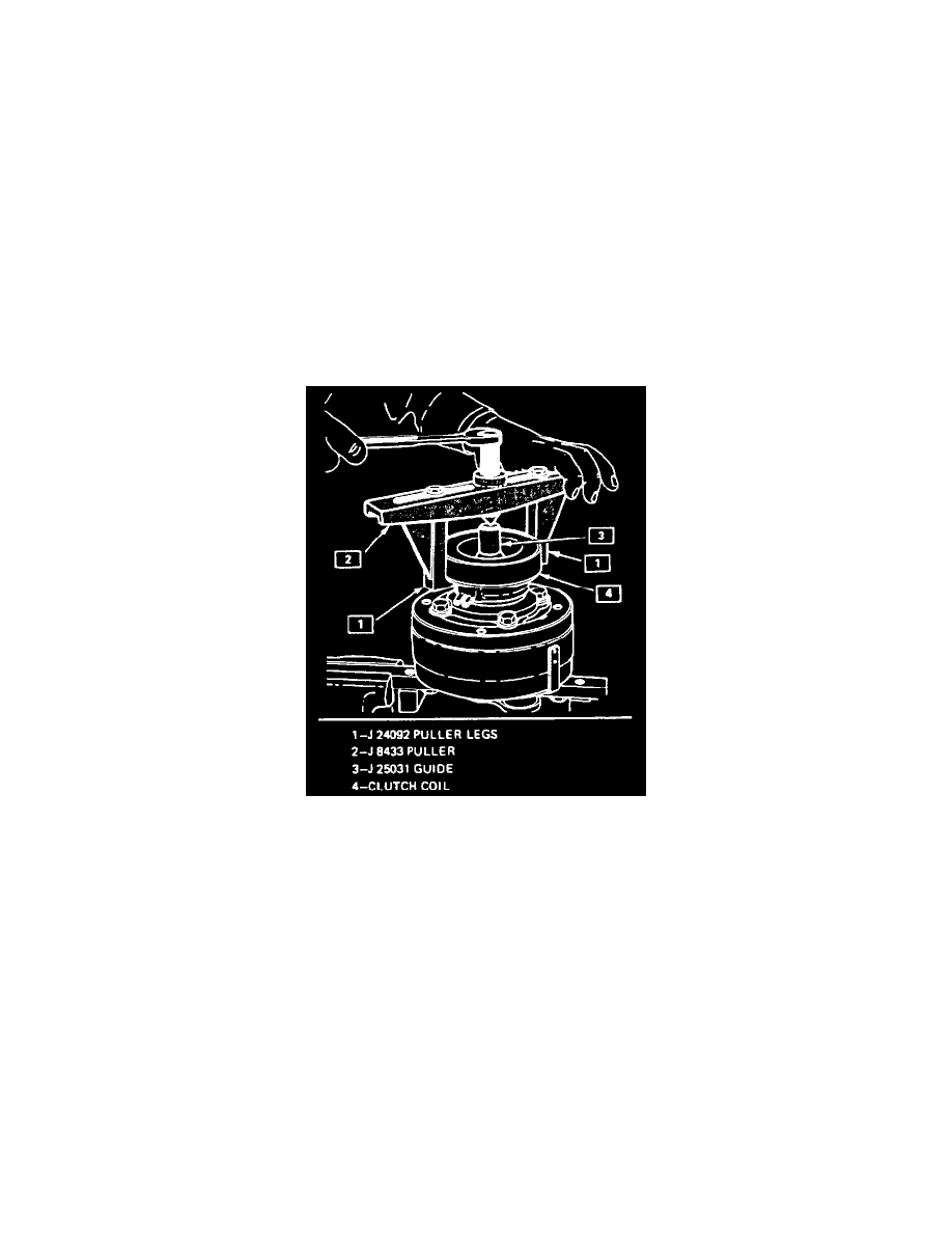
2. Remove the pulley rotor and bearing assembly as described previously. Mark the location of the clutch coil terminals on the compressor.
Removing Poly-Groove Clutch Coil