
S15/T15 Jimmy 2WD V6-262 4.3L VIN Z (1994)
Throttle Position Sensor: Description and Operation
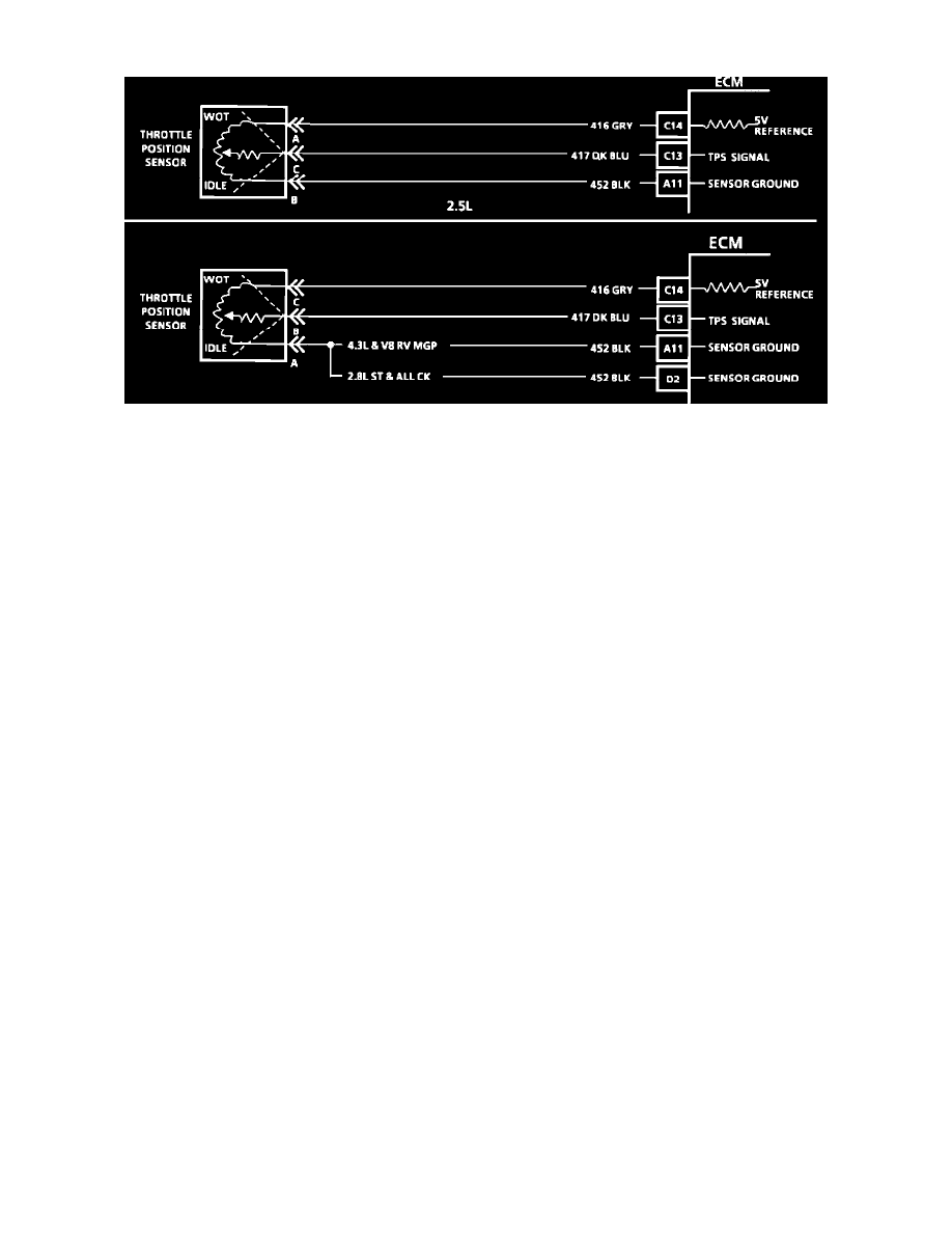
Wiring Diagram For Code 21 - Throttle Position Sensor (Signal Voltage High)
NOTE Because different models and engine applications vary in wire colors, circuit numbers, and pin numbers, the above image is a typical example.
Refer to COMPUTERS AND CONTROL SYSTEMS/SCHEMATIC AND ROUTING DIAGRAMS for specific schematic applications.
PURPOSE
The Throttle Position Sensor (TPS) is a potentiometer that senses throttle angle and sends a signal to the PCM. The TP signal is one of the most
important inputs used by the control module for fuel control and for most of the control module control outputs.
OPERATION
The TPS has three internal circuits provided by the control module. One to ground, a second from the control module as a 5.0 volt reference source
and a third circuit is used by the control module to measure the output voltage. As the throttle angle changes (pressing down on accelerator pedal) the
TPS voltage output varies from about .5 volt at idle to about 4.9 volts at wide open throttle (WOT).
Each time the voltage drops below 1.25 volts and stops, the control module assumes this value is 0 throttle from this point on.
LOCATION:
Side of throttle body opposite of throttle lever.