
S15/T15 Jimmy 2WD V6-262 4.3L VIN Z (1994)
Knock Sensor Circuit
Circuit Description
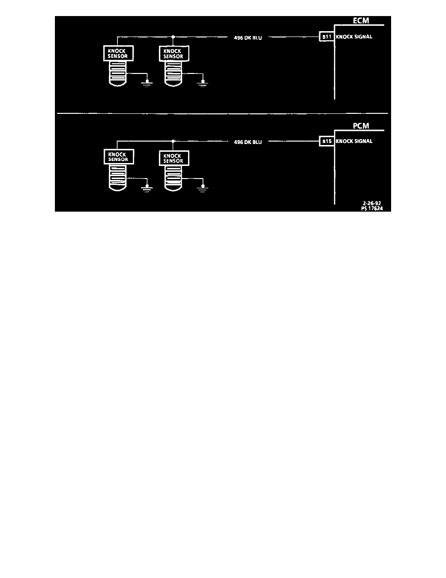
The Knock Sensor (KS) circuit consists of two knock sensors with one wire that goes directly to the control modules. There are two Knock Sensor
(KS) checks performed by the ECM. One check consists of monitoring CKT 496 for a voltage that is more than .63 volt and less than 3.1 volts.
If voltage is either too high or too low for 10 or more seconds, DTC 43 will set. The PCM uses this self check only. The next test is used only by the
ECM along with the previous test. Once engine temperature reaches 85°C, MAP is over 83 kPa, and engine speed is less than 3200 RPM, the ECM
will perform a self check. This self check will advance the timing until it receives a knock signal. If no knock signal is received, DTC 43 will set.
Chart Test Description
Number(s) below refer to circled number(s) on the diagnostic chart.
1. The first test is to determine if the system is functioning at the present time.
2. Test two determines the state of the 5 volt reference voltage applied to the knock sensor circuit.
3. Test 3 determines the state of the knock sensors and connections themselves.
Diagnostic Aids
The control module applies 5 volts to CKT 496. A 8200 ohm resistor in the knock sensors reduces the voltage to about 2.5 volts. When knock
occurs, the knock sensor produces a small AC voltage that rides on top of the 2.5 volts already applied. An AC voltage monitor, in the control
module, is able to read this signal as knock and incrementally retard spark. If the KS system checks OK, but detonation is the complaint, refer to
"Detonation/Spark Knock". See: Computers and Control Systems/Testing and Inspection/Symptom Related Diagnostic Procedures/Detonation/
Spark Knock