
S15/T15 Jimmy 2WD V6-4.3L VIN W (1998)
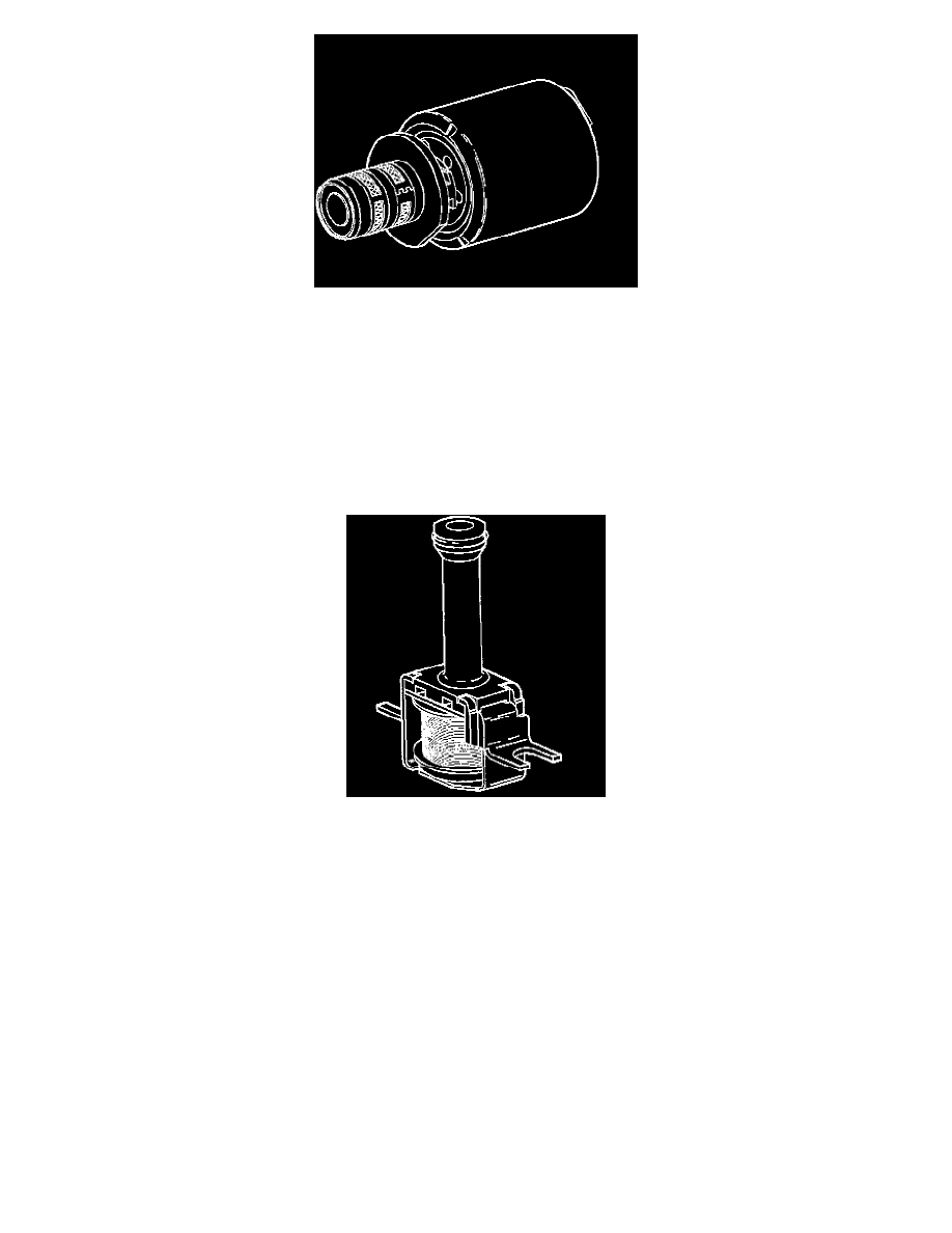
TRANSMISSION PRESSURE CONTROL SOLENOID
IMPORTANT: Transmission pressure control solenoid resistance should measure 3-5 ohms when measured at 20°C (68°F). The transmission
pressure control solenoid is an electronic pressure regulator that controls pressure based on the current flow through its coil winding. The magnetic
field produced by the coil moves the solenoid's internal valve which varies pressure to the pressure regulator valve.
The Powertrain Control Module (PCM) controls the pressure control solenoid by commanding current between 0.1 and 1.1 amps. This changes the
duty cycle of the solenoid, which can range between 5 percent and 95 percent (typically less than 60 percent). 1.1 amps corresponds to minimum line
pressure, and 0.1 amps corresponds to maximum line pressure (if the solenoid loses power, the transmission defaults to maximum line pressure).
The PCM commands the line pressure values, using inputs such as the throttle position sensor.
The pressure control solenoid takes the place of the throttle valve or the vacuum modulator that was used on the past model transmissions. If the duty
cycle drops below 5 percent or rises above 95 percent, DTC P0748 will set.
TORQUE CONVERTER CLUTCH SOLENOID VALVE
IMPORTANT: The Torque Converter Clutch (TCC) solenoid resistance should be 21-26 ohms minimum when measured at 20°C (68°F).
If a fault is detected in the TCC solenoid circuit, code P0740 will set.
The torque converter clutch solenoid valve is a normally open exhaust valve that is used to control torque converter clutch apply and release. When
grounded (energized) by the Powertrain Control Module (PCM), the TCC solenoid valve stops converter signal oil from exhausting. This causes
converter signal oil pressure to increase and shifts the TCC solenoid valve into the apply position.
The brake switch is an input to the PCM, and the PCM directly controls the TCC apply based on the brake switch status.