
S15/T15 Jimmy 2WD V6-4.3L VIN W (1998)
1. Clean all the gauge parts.
2. Lubricate the front and rear pinion bearings with axle lubricant.
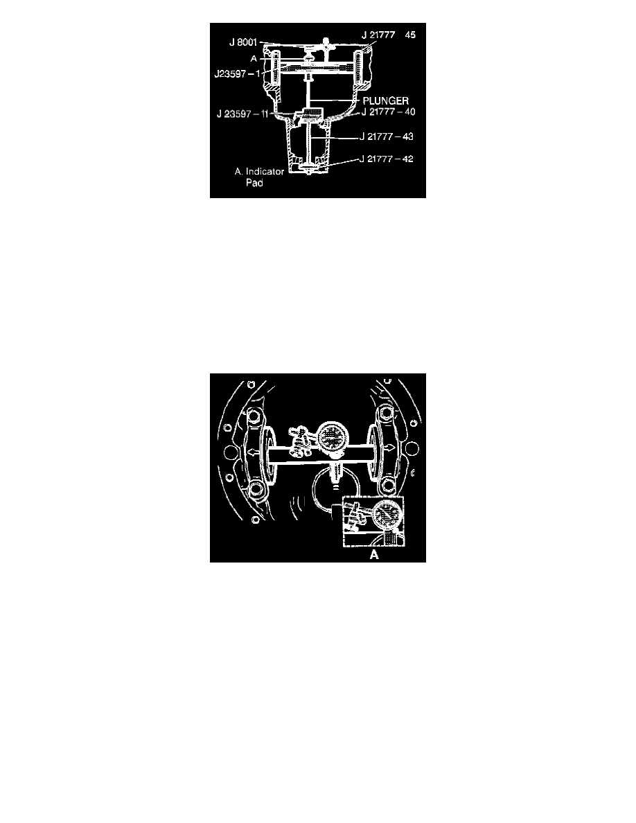
3. Place the bearings into the pinion bearing cups. Install the J 21777-40, the J 21777-42, the J 21777-43, and the J 23597-11 into the pinion bore.
4. Hold the stud stationary at the flats of the stud.
-
Tighten the stud nut to 2.2 Nm (20 inch lbs.).
NOTICE: Refer to Fastener Notice in Service Precautions.
5. Rotate the gauge plate and bearings several complete revolutions in order to seat the bearings.
6. In order to keep the gauge plate in rotation, torque the stud nut to 1.6 - 2.2 Nm (15 - 25 inch lbs.).
-
Tighten the stud nut to 1.6 - 2.2 Nm (15 - 25 inch lbs.).
7. Assemble the J 21777-45, the J 23597-11, and the J 8001 to the differential bearing bores. The bores must be clean and free of burrs.
8. Install the side bearing caps.
9. Tighten the bolts finger tight.
10. Rotate the gauge plate until the gauging areas are parallel with the discs.
11. Position the gauge shaft assembly in the carrier so that the dial indicator rod is centered on the gauge area of the gauge block.
12. Set the dial indicator at zero. Push the indicator shaft down until the needle rotates approximately 3/4 turn clockwise. Tighten the dial indicator in
this position.
13. Slowly rotate the gauge shaft back and forth until the dial indicator reads the greatest deflection. This shows when the indicator needle is centered.
14. Set the dial indicator to zero, at the point of greatest deflection. Repeat the rocking action of the gauge shaft in order to verify the zero reading.
15. Rotate the gauge shaft until the dial indicator rod does not touch the gauge block.
16. Record the actual number on the dial indicator. Do not record the number that represents how far the needle travels. This value is the nominal
pinion setting.
EXAMPLE: If the indicator needle moved counterclockwise 1.70 mm (0.067 inch) to a dial reading of 0.84 mm (0.033 inch), record the dial
reading of 0.84 mm (0.033 inch). Do not record the reading of1.70 mm (0.067 inch). The dial indicator should be within the 0.50 - 1.27 mm
(0.020 - 0.050 inch) range.
17. All drive pinion gears are manufactured to a nominal depth with no markings. The dial indicator reading is the shim selection.
18. Remove the bearing caps and depth gauging tools.
19. Install the correct pinion shim to the pinion.