
S15/T15 Sonoma P/U 2WD V6-262 4.3L VIN W CPI (1994)
Short And Grounded Circuit
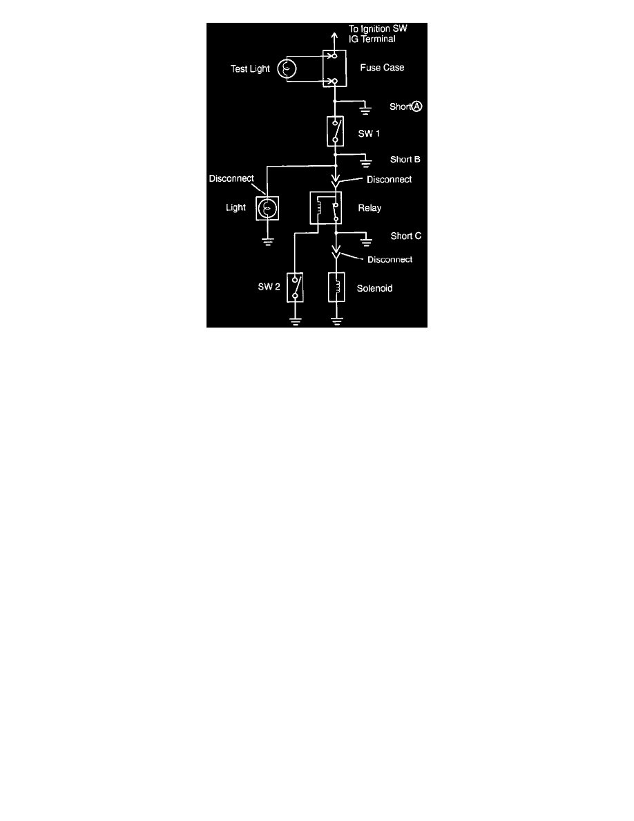
a. Remove the blown fuse and disconnect all loads of the fuse.
b. Connect a test light in place of the fuse.
c. Establish conditions in which the test light comes on.
Example:
A - Ignition SW ON
B - Ignition SW and SW 1 ON
C - Ignition SW, SW 1 and Relay on (Connect the Relay) and SW 2 OFF (or Disconnect SW 2)
d. Disconnect and reconnect the connectors while watching the test light. The short lies between the connector where the test light stays light and the
connector where the light goes out.
e. Find the exact location of the short by lightly shaking the problem wire along the body.
Intermittents and Poor Connections
Most intermittents are caused by faulty electrical connections or wiring, although occasionally a sticking relay or solenoid can be a problem. Some items
to check are:
^
Poor mating or connector halves, or terminals not fully seated in the connector body (backed out).
^
Dirt or corrosion on the terminals. The terminals must be clean and free of any foreign material which could impede proper terminal contact.
^
Damaged connector body, exposing the terminals to moisture and dirt, as well as not maintaining proper terminal orientation with the component
or mating connector.
^
Improperly formed or damaged terminals. All connector terminals in problem circuits should be checked carefully to ensure good contact tension.
Use a corresponding mating terminal to check for proper tension. Refer to "Checking Terminal Contact" for the specific procedure.
^
The J 35616-A Connector Test Adapter Kit must be used whenever a diagnostic procedure requests checking or probing a terminal. Using the
adapter will ensure that no damage to the terminal will occur, as well as giving an idea of whether contact tension is sufficient. If contact tension
seems incorrect, Refer to "Checking Terminal Contact" for specifics. See: General Troubleshooting Procedures/Checking Terminal Contacts
Wiring Problems
^
Poor terminal-to-wire connection. Some conditions which fall under this description are poor crimps, poor solder joints, crimping over wire
insulation rather than the wire itself, corrosion in the wire-to-terminal contact area, etc.
^
Wire insulation which is rubbed through, causing an intermittent short as the bare area touches other wiring or parts of the vehicle.
^
Wiring broken inside the insulation. This condition could cause a continuity check to show a good circuit, but if only 1 or 2 strands of a
multi-strand-type wire are intact, resistance could be far too high.
To avoid any of the above problems when making wiring or terminal repairs, always follow the instructions for wiring and terminal repair outlined in the
following procedure.