
S15/T15 Sonoma P/U 2WD V6-262 4.3L VIN W CPI (1994)
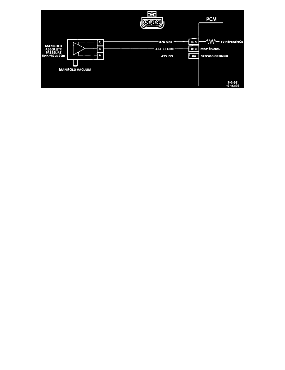
MAP Sensor Circuit
Circuit Description
The Manifold Absolute Pressure (MAP) sensor measures the changes in the intake manifold pressure which result from engine load (intake manifold
vacuum) and RPM changes; and converts these into a voltage output. The PCM sends a 5 volt reference voltage to the MAP sensor. As the manifold
pressure changes, the output voltage of the sensor also changes. By monitoring the sensor output voltage, the PCM knows the manifold pressure. A
lower pressure (low voltage) output voltage will be about 1 to 2 volts at idle. While higher pressure (high voltage) output voltage will be about 4 to
4.8 volts at Wide Open Throttle (WOT). The MAP sensor is also used, under certain conditions, to measure barometric pressure, allowing the PCM
to make adjustments for altitude changes. The PCM uses the MAP sensor to control fuel delivery and ignition timing.
Chart Test Description
Number(s) below refer to circled number(s) on the diagnostic chart.
Important
^ Be sure to use the same diagnostic test equipment for all measurements.
1. When comparing scan readings to a known good vehicle, it is important to compare vehicles that use a MAP sensor having the same color
insert and the same "Hot Stamped" number. Refer to Figures 1 and 2 on facing page.
2. Applying 34 kPa (10" Hg) vacuum to the MAP sensor should result in voltage readings of 1.5 to 2.1 volts less than the voltage in Step 1. Upon
applying vacuum to the sensor, the change in voltage should be instantaneous. A slow voltage change indicates a faulty sensor.
3. Check vacuum seal to sensor for leaking or restriction.
NOTICE:Make sure electrical connector remains securely fastened.
4. Remove sensor from the intake plenum and twist sensor (by hand only) to check for intermittent connection. Output changes greater than .10
volt indicate a faulty sensor or connection. If OK, replace sensor.