
S15/T15 Sonoma P/U 2WD V6-262 4.3L VIN W CPI (1994)
Differential Carrier: Adjustments
9 1/2 Inch Ring Gear
Final Assembly and Adjustment
1.
Lubricate side bearings, place outer races over bearings, then install differential assembly into housing.
2.
Insert spacer/shim packs removed during disassembly between respective bearing race and housing or threaded adjuster.
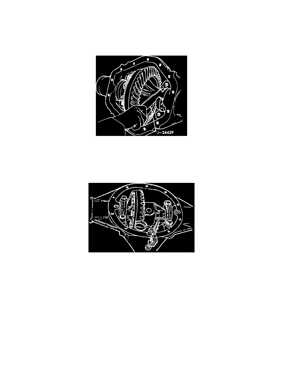
Fig. 10 Side Bearing Preload Adjustment
3.
Push case away from adjuster, then tighten adjuster,
Fig. 10, while rotating pinion and supporting case to seat bearings.
4.
Back off adjuster and loosely install bearing caps.
5.
Tighten adjuster against side bearing until no clearance exists, then tighten adjuster 3 additional notches to set preload.
6.
Torque bearing cap bolts to 70 ft. lbs., install adjuster locks and tighten lock bolt hand tight.
At this point, differential bearing preload is
properly adjusted. If any further adjustments are required, ensure that proper preload remains established.
Fig. 11 Ring gear & pinion backlash measurement
7.
Mount suitable dial indicator on housing with plunger contact bearing against heel of ring gear tooth and plunger parallel to gear,
Fig. 11.
8.
Hold pinion and rock ring gear back and forth, observing backlash on dial indicator.
9.
If backlash is not within specifications, adjust as follows:
a. If backlash is excessive, replace shim on ring gear tooth side with one of less thickness while increasing thickness of opposite shim by an
equal amount.
b. If backlash is less than specified, increase thickness of shim on ring gear tooth side while reducing opposite shim by an equal amount.
10.
After adjusting backlash, ensure that preload is properly established, then tighten adjuster lock bolt.
11.
Ensure that ring gear teeth are clean and free from oil, then coat drive and coat face of each tooth with suitable marking compound.
12.
Apply braking force to ring gear, then turn pinion to rotate ring gear one revolution in each direction.
Accurate contact pattern cannot be
obtained unless gears are ``loaded'' when rotated.