
Safari Van AWD V6-262 4.3L VIN W CPI (1992)
allowing the control module to make adjustments for different altitudes. The control module uses the MAP sensor to control fuel delivery and
ignition timing.
Test Description:
Numbers below refer to circled numbers on the diagnostic chart.
Important
^
Be sure to use the same diagnostic test equipment for all measurements.
1. Checks MAP sensor output voltage to the control module. This voltage, without engine running, represents a barometer reading to the control
module.
^
When comparing Tech 1 "Scan" readings to a known good vehicle, it is important to compare vehicles that use a MAP sensor having the
same color insert or having the same "Hot Stamped" number.
2. Applying 34 kPa (10" Hg) vacuum to the MAP sensor should cause the voltage to change. Subtract second reading from the first. Voltage
value should be greater than 1.5 volts. Upon applying vacuum to the sensor, the change in voltage should be instantaneous. A slow voltage
change indicated a faulty sensor.
3. Check vacuum hose to sensor for leaking or restriction. Be sure that no other vacuum devices are connected to the MAP hose.
NOTE: Make sure electrical connector remains securely fastened.
4. Disconnect sensor from bracket and twist sensor by hand (only) to check for intermittent connection. Output changes greater than .1 volt
indicates a bad connector or connection. If OK replace sensor.
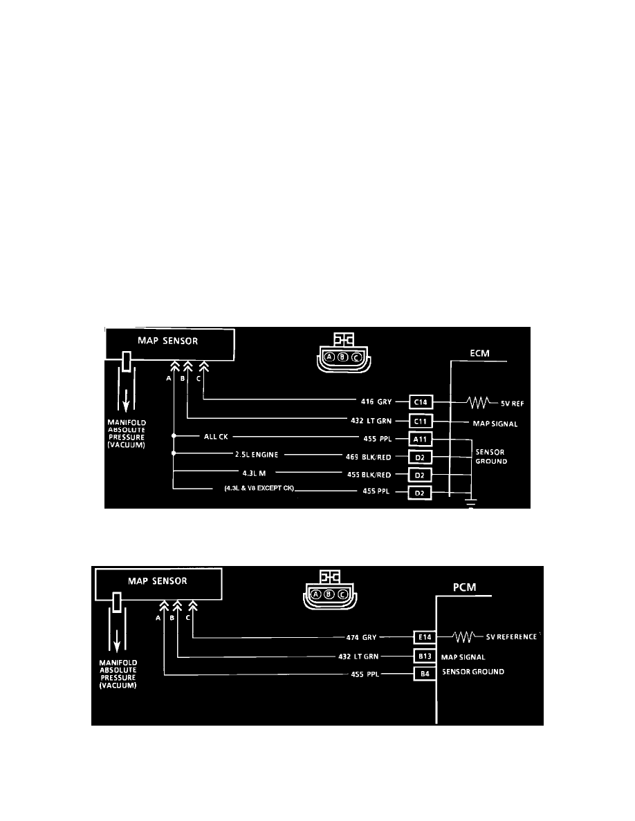
Wiring Diagram For Code 33 - MAP Sensor Circuit (Signal Voltage High - Low Vacuum)
ECM Circuit
MAP Sensor Circuit (PCM)
PCM Circuit