
Safari Van AWD V6-4.3L VIN W (1996)
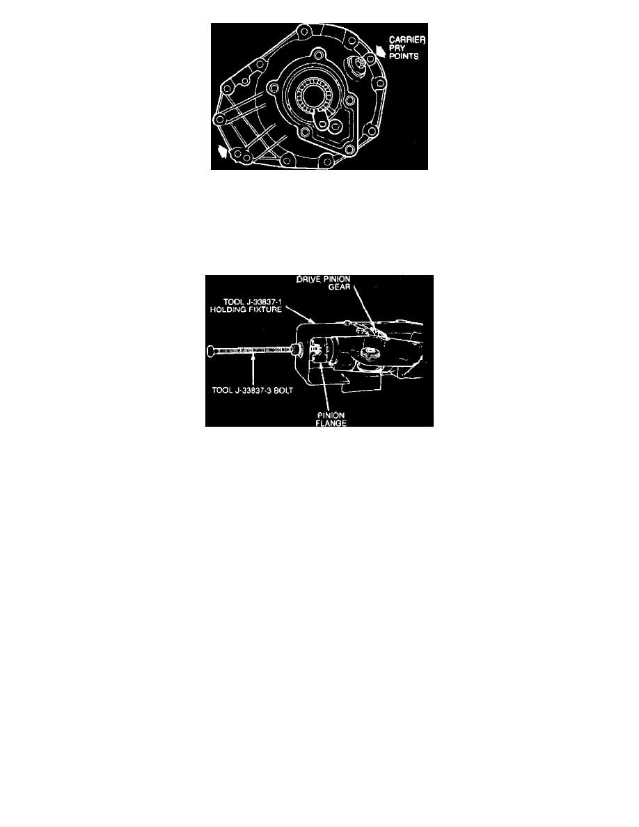
Fig. 2 Differential carrier pry points
4.
Remove the ten bolts holding carrier cover halves together, then insert screwdriver in slots, Fig. 2, and pry cover halves apart.
5.
Remove differential case from carrier. For service procedures on the differential case, refer to Disassembly/Assembly. See:
Disassembly/Assembly
6.
Remove the two side bearing adjusting locks.
7.
Remove both differential side bearing races by using tool J-33792 to turn adjusting sleeve until race is pushed out of carrier.
Fig. 3 Drive pinion removal
8.
Remove pinion flange nut using tool J-8614-01, then install pinion fixture tool J-33837, Fig. 3.
9.
Remove pinion from carrier by turning bolt on tool J-33837-1, Fig. 3, then remove pinion flange.
10.
Install tool J-33837-6 on tool J-33837-1, then remove outer pinion bearing, pinion bearing race and pinion seal.
11.
Install tool J-33837-6 on tool J-33837 and remove inner pinion bearing race from carrier.
12.
Remove inner drive pinion using tool J-22912-01.
ASSEMBLY
Lubricate all bearings, races and seals with axle lubricant before installing in differential.
1.
Install outer pinion bearing race, then the inner race using tool J-33837-4 until races are fully seated in carrier.
2.
Set pinion depth and install correct shim on drive pinion. Refer to Pinion Gear / Adjustments. See: Pinion Gear/Adjustments
3.
Install inner pinion bearing on pinion using tool J-33785.
4.
Install a new collapsible spacer on pinion, then position the pinion assembly in carrier.
5.
Install outer pinion bearing in carrier, then install bearing seal using tool J-33782.
6.
Install pinion flange, washer and nut, then install holder tool J-8614-01 on flange and tighten nut until no endplay is detectable.
7.
Check preload and set to 15-25 inch lbs. using an inch-pound torque wrench. When setting preload, tighten pinion nut only a little at a time
and recheck setting frequently. If preload specifications are exceeded, the collapsible spacer will be compressed beyond limits and will
have to be replaced.
8.
Rotate pinion several times to make sure that bearings have been seated, then recheck preload and correct as necessary.
9.
Install output shaft bearings and adjusting sleeves in inserts in carrier and tighten finger tight.
10.
Install differential side bearing race into carrier using tool J-23423-A. If differential output shaft bearings or adjusting sleeve inserts must be
replaced, proceed as follows:
a. Remove differential output shaft bearing from adjusting sleeve using tool J-21551.
b. Install new bearings into adjusting sleeves using tool J-33788.
c. Install sleeve and bearing into insert and tighten finger tight, then install complete assembly into carrier using tool J-23423-A.
11.
Install differential case in carrier, then, adjust differential backlash. Refer to Differential Carrier / Adjustments. See: Adjustments
12.
Install left hand carrier cover seal using tool J-23914. Support cover when installing seal to avoid bending the cover.
13.
Apply sealer No. 1052366, or equivalent, to carrier mating surface, then install cover. Torque bolts to 15-20 ft. lbs.